18. TROUBLESHOOTING
18.2 Error Message and System Alarm
18 - 11
17
MA
INTENA
N
C
E
AND
IN
SPE
CTIO
N
18
T
ROUBL
ESHOOT
ING
APP
ENDICES
18.2 Error Message and System Alarm
This chapter describes the error message and system alarm displayed in the GOT.
As the error code and error message displaying functions when an error occurs at the GOT, controller or network, there
are two kinds: system alarm and advanced system alarm.
For details of the system alarm and advanced system alarm, refer to the following.
GT Designer3 Version1 Screen Design Manual (Functions)
POINT
POINT
POINT
Error code and channel No.
• Error codes can also be confirmed in the error code storage area of the system information function.
• The channel No. where an error is occurring can be confirmed with the GOT special register (GS262 to 264).
For details of the system information and GOT special register, refer to the following manual.
GT Designer3 Version1 Screen Design Manual (Fundamentals)
18.2.1 Error contents display
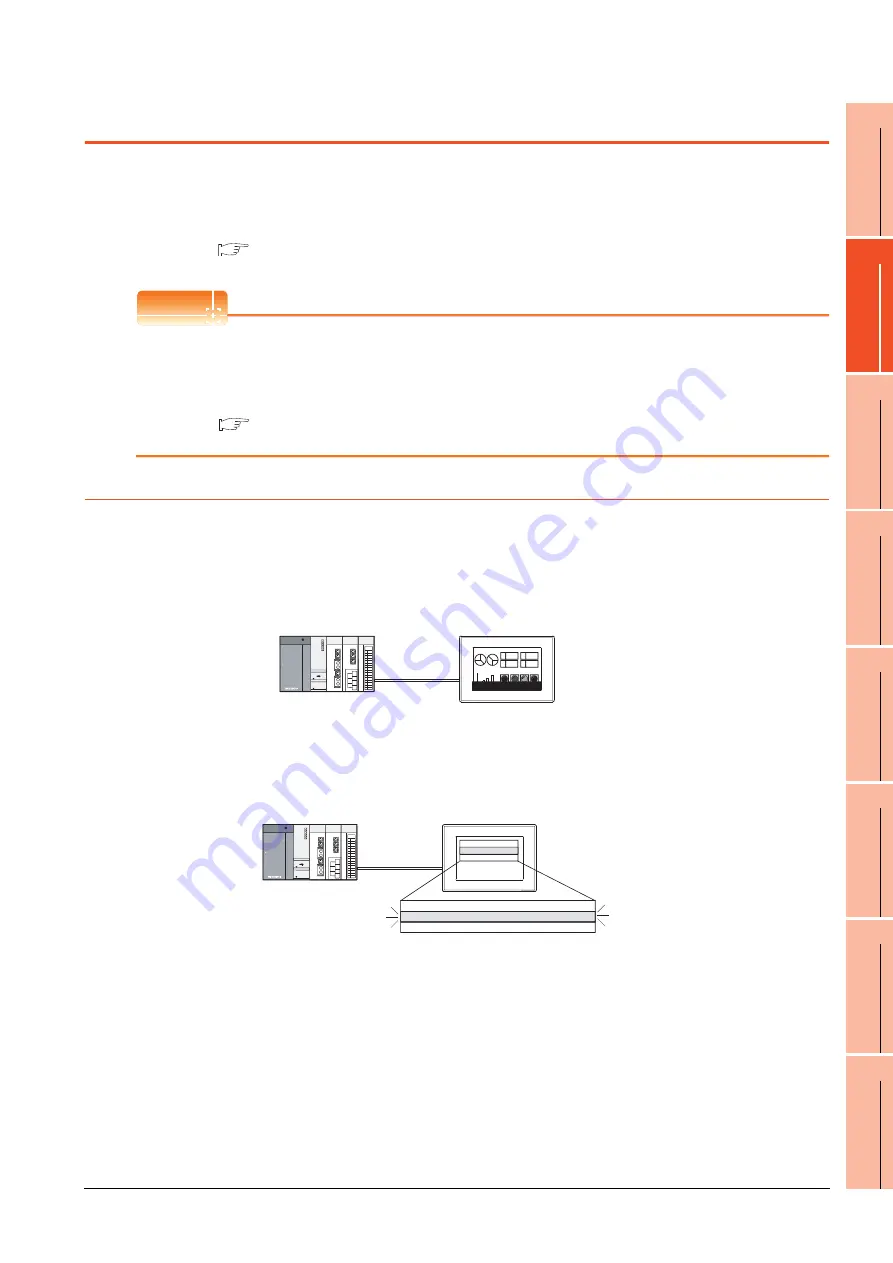
This section describes the example for displaying error code and error message on GOT.
Popup-displaying the error code and error message (Advanced alarm popup display
(System alarm))
If an error occurs, the error code and error message can be popup-displayed on the front of the monitor screen.
As alarms are popup-displayed regardless of the screen type, the error occurred will not be overlooked.
Displaying error code and error message in a list (Advanced system alarm display)
If error has occurred, error code and error message can be displayed on the list set with the screen.
Multiple errors can be displayed, or the history of display can be recorded.
A 1254
348
B
A 1254
348
B
04/6/1 13:20 Power module
Pop up generated alarms
regardless of the screen.
04/6/1 8:05
Fuse error
Occurred
Message
Restore
Check
04/6/1 10:25
Temp. error
Create a screen to display alarms, and confirm
the details of the alarms and take measures.
11:25 10:45
Summary of Contents for Got 1000
Page 1: ......
Page 2: ......
Page 14: ...A 12 ...
Page 26: ...1 4 1 OVERVIEW 1 1 Features ...
Page 34: ...2 8 2 SYSTEM CONFIGURATION 2 2 System Equipment ...
Page 38: ...3 4 3 SPECIFICATIONS 3 3 Power Supply Specifications ...
Page 42: ...4 4 4 PARTS NAME 4 3 Rear Face ...
Page 54: ...6 6 6 INSTALLATION 6 5 Installation Procedure ...
Page 104: ...10 18 10 COMMUNICATION INTERFACE SETTING COMMUNICATION SETTING 10 3 Ethernet Setting ...
Page 226: ...13 92 13 FILE DISPLAY AND COPY PROGRAM DATA CONTROL 13 2 Various Data Control ...
Page 250: ...15 2 15 CLEANING DISPLAY SECTION CLEAN ...
Page 264: ...16 14 16 INSTALLATION OF COREOS BOOTOS AND STANDARD MONITOR OS 16 5 CoreOS ...
Page 272: ...17 8 17 MAINTENANCE AND INSPECTION 17 5 Backlight Shutoff Detection ...
Page 298: ...App 6 APPENDICES Appendix 1 External Dimensions ...
Page 302: ...App 10 APPENDICES Appendix 3 Transportation Precautions ...
Page 306: ...REVISIONS 2 ...
Page 309: ......
Page 310: ......


