


11. DISPLAY AND OPERATION SETTINGS (GOT SET UP)
11.4 Backup/Restoration Setting
11 - 19
9
UTILIT
Y
FUNCTION
10
C
O
MM
UNICA
TIO
N
IN
TE
RF
AC
E S
ETTING
(CO
M
MUN
ICA
TION
S
ETTIN
G
)
11
DI
SPL
A
Y
AN
D
OPERA
T
ION S
E
TTINGS
(G
OT SE
T UP)
12
C
LOC
K SET
TI
N
GS
AN
D
BA
TT
ER
Y ST
AT
U
S D
IS
PL
AY
(T
IM
E SET
TI
N
G
A
N
D
D
ISPL
AY)
13
FILE
D
ISP
LA
Y A
N
D
C
O
PY
(P
RO
GR
AM
/D
A
TA
CONTR
O
L
)
14
GO
T
SE
LF
CHE
CK
(DEB
UG AND
S
E
LF
CHECK)
15
CLEA
NING DISPL
A
Y
SE
CT
ION (CLE
AN)
16
INST
ALLA
TION OF
C
O
REOS, BOOT
OS
A
N
D
ST
AN
DA
RD
MO
NI
T
O
R
OS
11.4 Backup/Restoration Setting
The storage location for backup data can be set.
For how to use the backup/restoration, refer to the following manual.
GOT1000 Series Extended/Option Functions Manual for GT Works3
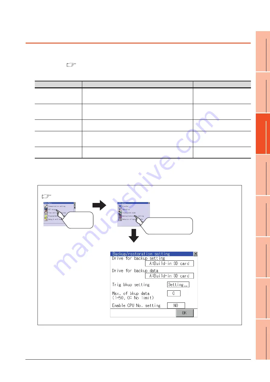
Set the following items with touching the items on the GOT.
Display operation of Backup/restoration setting
Item
Description
Setting range
Drive for backup setting
The drive for storing backup settings, including parameters and passwords
for controllers, can be selected.
A: Built-in SD Card
E: USB memory
(Default: A: Built-in SD Card)
Drive for backup data
The drive for storing backup data can be selected.
A: Built-in SD Card
E: USB memory
(Default: A: Built-in SD Card)
Trigger backup setting
The GOT automatically backs up data when triggers (Rise, Time) specified
for each backup setting are met.
None/Rise/Time
(Default: None)
Max. of backup data
Set the maximum number of backup data to be stored.
(When 0 is specified, the GOT does not check the number of backup data to
be stored.)
Setting range: 0 to 50
(Default: 10)
Enable CPU No. setting
Set the CPU No. setting at backup to "YES" or "NO".
YES/NO
(Default: NO)
GOT setup
Touch
[GOT setup]
Touch
[Backup/restoration setting]
Main menu
Backup/restoration setting
(
Summary of Contents for Got 1000
Page 1: ......
Page 2: ......
Page 14: ...A 12 ...
Page 26: ...1 4 1 OVERVIEW 1 1 Features ...
Page 34: ...2 8 2 SYSTEM CONFIGURATION 2 2 System Equipment ...
Page 38: ...3 4 3 SPECIFICATIONS 3 3 Power Supply Specifications ...
Page 42: ...4 4 4 PARTS NAME 4 3 Rear Face ...
Page 54: ...6 6 6 INSTALLATION 6 5 Installation Procedure ...
Page 104: ...10 18 10 COMMUNICATION INTERFACE SETTING COMMUNICATION SETTING 10 3 Ethernet Setting ...
Page 226: ...13 92 13 FILE DISPLAY AND COPY PROGRAM DATA CONTROL 13 2 Various Data Control ...
Page 250: ...15 2 15 CLEANING DISPLAY SECTION CLEAN ...
Page 264: ...16 14 16 INSTALLATION OF COREOS BOOTOS AND STANDARD MONITOR OS 16 5 CoreOS ...
Page 272: ...17 8 17 MAINTENANCE AND INSPECTION 17 5 Backlight Shutoff Detection ...
Page 298: ...App 6 APPENDICES Appendix 1 External Dimensions ...
Page 302: ...App 10 APPENDICES Appendix 3 Transportation Precautions ...
Page 306: ...REVISIONS 2 ...
Page 309: ......
Page 310: ......


