


8. OPTION
8.6 USB Environmental Protection Cover
8 - 9
1
OV
E
R
VI
EW
2
S
YSTE
M
CONF
IGURA
TION
3
SPEC
IFI
CA
TIO
NS
4
PA
R
T
S
N
A
M
E
5
UL, cUL
ST
ANDARDS AND
EMC DIRECTIVE
6
IN
ST
AL
L
A
TI
ON
7
WIRING
8
OP
TI
ON
8.6 USB Environmental Protection Cover
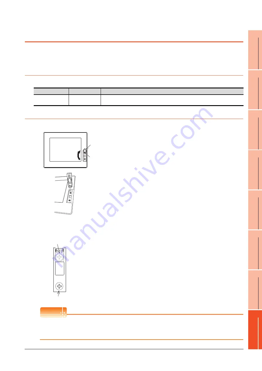
The USB environmental protection cover protects the USB connector on the front face of GOT from dust, water, and oil.
The GOT is installed with the USB environmental protection cover at factory shipment.
Replace when damage and deterioration are caused.
8.6.1
Applicable USB environmental protection cover
The following USB environmental protection cover is applicable for GT14.
8.6.2
Installing procedure
POINT
POINT
POINT
Precautions when the USB environmental protection cover is opened
Environmental protective structure of USB interface is "IP2X" when the USB environmental protection cover is
opened.
Product name
Model name
Description
USB environmental
protection cover
GT14-50UCOV
Environmental protection cover for USB interface on the main unit front panel (conforming to IP67f)
1.
Turn the GOT power off.
2.
Disconnect the USB cable from the GOT if one is
connected.
3.
Open the USB environmental protection cover
equipped with the GOT and remove the mounting
screws.
4.
Remove the old USB environmental protection cover
from the GOT to replace it with the new USB
environmental protection cover.
5.
Fix the projection of the new USB environmental
protection cover to be fitted into the hole of the GOT,
tighten the mounting screw in the specified torque
range, then install it to the GOT.
Tighten the mounting screws in the specified torque
range.
Not doing so may cause a damage or a drop.
Specified torque range: 0.36 to 0.48N·m
Mounting screw
Open
USB environmental
protection cover
Mounting screw
M3 x 6 pan head screw
M3 x 6 pan head screw
Summary of Contents for Got 1000
Page 1: ......
Page 2: ......
Page 14: ...A 12 ...
Page 26: ...1 4 1 OVERVIEW 1 1 Features ...
Page 34: ...2 8 2 SYSTEM CONFIGURATION 2 2 System Equipment ...
Page 38: ...3 4 3 SPECIFICATIONS 3 3 Power Supply Specifications ...
Page 42: ...4 4 4 PARTS NAME 4 3 Rear Face ...
Page 54: ...6 6 6 INSTALLATION 6 5 Installation Procedure ...
Page 104: ...10 18 10 COMMUNICATION INTERFACE SETTING COMMUNICATION SETTING 10 3 Ethernet Setting ...
Page 226: ...13 92 13 FILE DISPLAY AND COPY PROGRAM DATA CONTROL 13 2 Various Data Control ...
Page 250: ...15 2 15 CLEANING DISPLAY SECTION CLEAN ...
Page 264: ...16 14 16 INSTALLATION OF COREOS BOOTOS AND STANDARD MONITOR OS 16 5 CoreOS ...
Page 272: ...17 8 17 MAINTENANCE AND INSPECTION 17 5 Backlight Shutoff Detection ...
Page 298: ...App 6 APPENDICES Appendix 1 External Dimensions ...
Page 302: ...App 10 APPENDICES Appendix 3 Transportation Precautions ...
Page 306: ...REVISIONS 2 ...
Page 309: ......
Page 310: ......


