


10 - 8
10. COMMUNICATION INTERFACE SETTING (COMMUNICATION SETTING)
10.2 Communication Detail Setting
10.2 Communication Detail Setting
10.2.1 Communication detail setting functions
10.2.2 Display operation of Communication Detail setting
Communication settings
POINT
POINT
POINT
Communication parameter setting by drawing software
Select [Common Settings] [Communication Settings] from GT Designer3 to enter the communication
parameters for each communication driver.
When changing the communication parameters after downloading project data, change the setting at
communication detail setting of GOT.
GT Designer3 Version1 Screen Design Manual (Fundamentals)
Function
Description
Communication parameters
setting
Set various communication parameters of communication devices. The settable parameters differ according to the
communication device.
Keyword Register
For the FX series PLCs, key word for protecting program in the PLC can be set.
Keyword Delete
For the FX series PLCs, key word for protecting program in the PLC can be deleted.
Keyword Clear
For the FX series PLCs, the program protection status in the PLC can be cancelled.
Keyword Protect
For the FX series PLCs with the 2nd keyword in use, the cancelled program protection in the PLC can be reactivated.
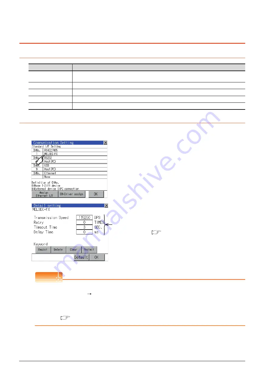
1.
Touch the driver display BOX of the communication
parameter to be set in the [Communication setting]
screen.
2.
The screen switches to the [Communication Detail
setting] screen.
Set communication parameters from this screen.
For the setting change operation, refer to the
following.
9.3.3 Basic operation of settings change
Communication
parameter
Summary of Contents for Got 1000
Page 1: ......
Page 2: ......
Page 14: ...A 12 ...
Page 26: ...1 4 1 OVERVIEW 1 1 Features ...
Page 34: ...2 8 2 SYSTEM CONFIGURATION 2 2 System Equipment ...
Page 38: ...3 4 3 SPECIFICATIONS 3 3 Power Supply Specifications ...
Page 42: ...4 4 4 PARTS NAME 4 3 Rear Face ...
Page 54: ...6 6 6 INSTALLATION 6 5 Installation Procedure ...
Page 104: ...10 18 10 COMMUNICATION INTERFACE SETTING COMMUNICATION SETTING 10 3 Ethernet Setting ...
Page 226: ...13 92 13 FILE DISPLAY AND COPY PROGRAM DATA CONTROL 13 2 Various Data Control ...
Page 250: ...15 2 15 CLEANING DISPLAY SECTION CLEAN ...
Page 264: ...16 14 16 INSTALLATION OF COREOS BOOTOS AND STANDARD MONITOR OS 16 5 CoreOS ...
Page 272: ...17 8 17 MAINTENANCE AND INSPECTION 17 5 Backlight Shutoff Detection ...
Page 298: ...App 6 APPENDICES Appendix 1 External Dimensions ...
Page 302: ...App 10 APPENDICES Appendix 3 Transportation Precautions ...
Page 306: ...REVISIONS 2 ...
Page 309: ......
Page 310: ......


