
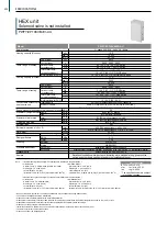


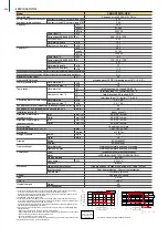
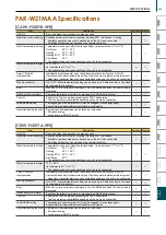


CAHV-P500YB-HPB
CAHV-P500YB-HPB
3-phase 4-wire 380-400-415V 50/60Hz
45
38,700
153,540
12.9
21.78 - 20.69 - 19.94
3.49
45
38,700
153,540
25.6
43.17 - 41.01 - 39.53
1.76
A++
A+
57.77 - 54.88 - 52.90
12.9kPa (1.87psi)
25~70°C
77~158°F
-20~40°C
-4~104°F
7.5 m³/h-15.0m³/h
59
63
38.1 (Rc 1 1/2") screw
38.1 (Rc 1 1/2") screw
Acrylic painted steel plate <MUNSELL 5Y 8/1 or similar>
1,710 (without legs 1,650) × 1,978 × 759
67.3 (without legs 65.0) × 77.9 × 29.9
511 (1127)
Y strainer Rc 1 1/2
3.85
1.0
KC94R746
KC94R745
stainless steal plate and copper brazing
Plate fin and copper tube
Inverter scroll hermetic compressor
MITSUBISHI ELECTRIC CORPORATION
Inverter
7.5 × 2
0.045 × 2
MEL32
185 × 2
3,083 × 2
6,532 × 2
0Pa, 60Pa (0mmH²O/6.1mmH²O)
Propeller fan × 2
Inverter-control, Direct-driven by motor
0.46 × 2
Copper pipe
High pres.Sensor & High pres.Switch at 3.85MPa (643psi)
Over-heat protection, Over current protection
Over-heat protection
Thermal switch
Auto-defrost mode (Reversed refrigerant circle)
LEV and HIC circuit
R407C
1,774
11.0
161.3
Power input
Current input
COP (kW / kW)
Power input
Current input
COP (kW / kW)
Outlet water temp *4
Outdoor temp *4
Inlet
Outlet
R407C
Water
Wiring
External
Water side
Air side
Type
Maker
Starting method
Motor output
Case heater
Lubricant
Air flow rate
External static press *5
Type × Quantity
Control, Driving mechanism
Motor output
High pressure protection
Inverter circuit
Compressor
Fan motor
Weight
CO
2
equivalent
kW
kcal/h
BTU/h
kW
A
kW
kcal/h
BTU/h
kW
A
A
D.B
dB (A)
dB (A)
mm (in.)
mm (in.)
mm
in.
kg (lbs)
MPa
MPa
kW
kW
m³/min
L/s
cfm
kW
Model
Power Source
Capacity *1
Capacity *2
Seasonal space heating energy efficiency class for medium-temperature application
Seasonal space heating energy efficiency class for low-temperature application
Maximum current input *3
Water pressure drop *1
Temp range
Circulating water volume range
Sound Pressure level (measured in anechoic room) *1
Sound Pressure level (measured in anechoic room) *3
Diameter of water pipe
External finish
External dimension H × W × D
Net weight
Accessories
Design Pressure
Drawing
Heat exchanger
Compressor
FAN
HIC circuit (HIC:Heat inter-Changer)
Protection
Defrosting method
Control
Type
GWP *6
Original charged
*1 Under Normal heating conditions at
outdoor temp, 7ºC DB/6ºC WB(44.6°F
DB/42.8°F WB) outlet water temp
45ºC(113°F), inlet water temp
40ºC(104°F)
*2 Under Heating conditions at outdoor temp,
7ºC DB/6ºC WB(44.6°F DB/42.8°F WB),
outlet water temp 70ºC (158°F)
*3 Under Heating conditions at outdoor temp,
7ºC DB/6ºC WB(44.6°F DB/42.8°F WB)
when this unit is set to capacity priority
mode by non-voltage B contact
*5 Dip SW on the unit control board need to be changed.
*6 This table is based on Regulation(EU) No517/2014
* Due to continuing improvement, the above specifications may be subject to change without notice.
* Please don't use the steel material for the water piping material.
* Please always make water circulate or pull out the circulation water completely when not using it.
* Please do not use groundwater and well water.
* Install the unit in an environment where the wet bulb temp will not exceed 32ºC (89.6°F).
* The water circuit must use the closed circuit.
kcal/h =kW × 860
BTU/h =kW × 3,412
cfm =m³/min × 35.31
lbs =kg/0.4536
Unit converter
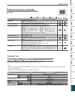
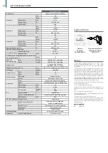
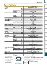
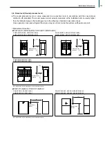
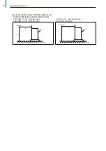
Outdoor temp -20°C DB/ Outlet water temp 40~65°C
(Outdoor temp -4°F DB/ Outlet water temp 104°F~149°F)
Outdoor temp -10°C DB/ Outlet water temp 33°C~70°C
(Outdoor temp 14°F DB/ Outlet water temp 91°F~158°F)
Outdoor temp 0°C DB/ Outlet water temp 25°C~70°C
(Outdoor temp 32°F DB/ Outlet water temp 77°F~158°F)
0
10
20
30
40
50
60
70
80
-30 -20 -10 0
10 20 30 40 50
outdoor temp (°C DB)
ou
tle
t w
at
er
te
m
p
(°
C
)
32
52
72
92
112
132
152
172
-22 -2
18
38
58
78
98 118
outdoor temp (°F DB)
ou
tle
t w
at
er
temp
(°
F)
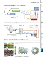
<External input/output from the unit>
*The unit can be operated and the operation
status can be monitored with
Specifications
*4
external input/output terminals.
233
SPECIFICATIONS
VRF
Y-Series
VRF
Lineup
VRF
R2-Series
VRF
Zubadan
VRF
WY-Series
VRF
WR2-Series
VRF
S-Series
VRF
Indoor Units
Ventilation
Systems
Technologies and Functions
Remote Controller
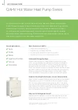
Hot Water Solution
VRF
BC Controllers
VRF
S-Series
Summary of Contents for City Multi R2 Series
Page 1: ...CM20AN E NZ VRF City Multi Product Catalogue ...
Page 101: ...BC Controllers 101 ...
Page 112: ...Indoor Units VRF 112 ...
Page 114: ...Ceiling Cassette Type 4 Way Airflow Type 114 ...
Page 122: ...Ceiling Cassette Type 2 Way Airflow Type 122 ...
Page 128: ...Ceiling Concealed Type 128 ...
Page 150: ...Wall Mounted Type 150 ...
Page 154: ...Floor Standing Type 154 ...
Page 181: ...Ventilation Systems 181 ...
Page 190: ...Remote Controllers 190 ...


