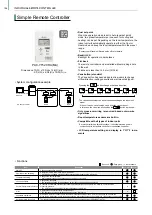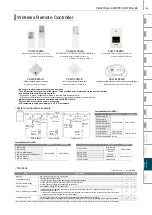
A control
M-NET
M-NET
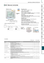
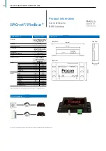
Dimensions: 180(W) x 120(H) x 30(D) mm
: 7-2/16(W) x 4-3/4(H) x 1-3/16(D) in.
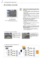
GRID (zoom out) screen
Displays the operation status
of all groups.
GRID (zoom in) screen
Displays the operation
status details of each group.
LIST screen
Displays the operation status
details of each group
by group name.
GROUP screen
Displays the operation
status details of each group.
Sets group operations.
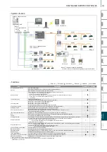
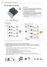
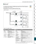
AT-50B
PAC-SC51KUA-J
Power supply unit
M-NET
adapter
DIDO controller
Lossnay
General equipment
• The color touch panel is easy to see and operate.
The operation screen can be selected according to the
intended use.
• Dual set point
When the operation mode is set to Auto (dual set point)
mode, two preset temperatures (one each for cooling and
heating) can be set. Depending on the room temperature,
the indoor unit will automatically operate in either the Cool
or Heat mode and keep the room temperature within the
preset range.
*Contact your Mitsubishi Electric sales office for details.
Preset temp.
(COOL)
Preset temp.
(HEAT)
Room
temperature
HEAT
HEAT
COOL
COOL
The room temperature
changes in accordance
with changes in the
outside temperature.
Dual
Set
Point
Dual
Set
Point
• System structure
• Operation pattern during Auto (dual set point) mode
AT-50B
Advanced Touch Controller AT-50B ensures easy and simple operation on the touch panel to offer an
optimal air environment by each unit.
A 5-inch color LCD (Liquid Crystal Display) touch panel enables easy and simple operation.
When the backlight is off, touching the panel turns it back on.
The touch panel displays the operation status of the units in GRID, LIST or GROUP form.
Backlit LCD touch panel
Advanced Touch Controller
1
Controls 50 indoor units
One screen shows the operation conditions of 50
connected indoor units.
Weekly and daily schedules
5 daily schedule patterns and 12 weekly schedule patterns
(max. 16 settings per pattern).
Two types of weekly schedules can be set.
System changeover
Operation mode can be switched depending on the indoor
temperature setting and target temperature of each group or
a representative indoor unit.
Functions
[Basic Functions]
▪
ON/OFF
▪
Operation mode switching
▪
Temperature setting
▪
Fan speed setting
▪
Airflow direction setting
▪
Louver setting
Item
Permit / Prohibit
Operation lock
Error display
Ventilation (independent)
Ventilation (interlocked)
The ON/OFF, operation mode, setting temperature, fan speed, air direction, filter sign reset operations, and timer
using the local remote controllers can be prohibited.
Only ON/OFF and filter reset can be prohibited for the Lossnay group.
*The settable items vary depending on the models.
The operation lock can be set to the input operation of the AT-50B.
Each button can be set. (Function Button 1, Function Button 2, Collective ON/OFF, Touch Panel)
Each function can be set. (Operation mode, Setting temperature, Fan speed, Menu button)
The password for the lock release can be set.
When an error is occurring on an air conditioner unit, the affected unit and the error code are displayed.
* When an error occurs, the "ON/OFF" LED flashes. The operation monitor screen shows an abnormal icon over the
unit. The error monitor screen shows the abnormal unit address and error code. The error log monitor screen shows
the time and date, the abnormal unit address, error code, and source of detection.
The Lossnay will run in interlock with the operation of the indoor unit.
The mode cannot be changed. The LED will turn ON during operation after interlocking.
Temperature set
limitation
Batch-setting to temperature range limit in cooling, heating, and auto modes.
This function cannot be used with the MA remote controller. (Depends on the indoor unit model.)
Specific mode operation
prohibit (Cooling prohibit,
heating prohibit, cooling/
heating prohibit)
When set as the main controller, operation of the following modes with the local remote controllers can be prohibited:
When cooling is prohibited: Cooling, dry, automatic can not be chosen.
When heating is prohibited: Heating, automatic can not be chosen.
When cooling/heating is prohibited: Cooling, dry, heating, automatic can not be chosen.
External input
(Emergency stop input, etc.)
The following input with level signals or pulse signals are available.
Level signal: "Emergency stop input" or "Collective ON/OFF"
Pulse signal: "Collective ON/OFF" or "Local remote controller prohibit/permit"
One input can be selected from those above.
* An external input/output adapter (PAC-YT51HAA (sold separately)) is required.
Relays and DC power supply or other devices must be prepared at the site.
External output
(Error output, operation output)
"ON/OFF" and "error/normal" are output with the level signal.
* An external input/output adapter (PAC-YT51HAA (sold separately)) is required.
Relays and DC power supply or other devices must be prepared at the site.
Checking the Gas Amount
Use this function to check for a refrigerant leak from the outdoor unit.
* When this function is used, the gas amount checking function of the outdoor unit cannot be used.
This function is for CITY MULTI R2 and Y (PUMY is excluded.) Series only.
Schedule operation
* Depending on the installation conditions, power supply unit (PAC-SC51KUA) is required. Please contact your local distributor or MITSUBISHI ELECTRIC branch office for further information.
Weekly schedule setting of up to 12 patterns is available.
In one pattern, up to 16 settings of "ON/OFF", "Operation mode", "Set Temperature", "Fan speed", "Air flow direction",
and "Permit / Prohibit local operation" can be scheduled.
Two types of weekly schedules (Summer/Winter) can be set. Today's schedule allows setting of up to 5 patterns.
Description
Operations
: Each unit : Each group : Group or collective : Not available
Display
Switches the mode "Bypass/Heat recovery/Auto" for Lossnay groups.
X
• Functions
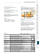
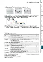
Night setback
When the room temperature goes outside a certain range
during a prespecified time period, this heating or cooling
operation is automatically activated to prevent dew
condensation or an excessive temperature increase in the
room.
Main system controller/Sub system
controller
The AT-50B can be used as the main or sub system
controller. When it is connected to a system controller such
as the AE-200E, it is used as a sub controller. When
multiple units of the AT-50B are connected, the main and
sub controllers can be specified.
Simple button arrangement
The F1 (Function 1) and F2 (Function 2) buttons can be
set as a run button for the following collective operations.
(Setback/Schedule/Operation mode/Temperature
correction/Disable remote controller operation)
Lower
temperature
limit
12°C/53°F
When the temperature drops below the lower temperature limit
(heating control)
21°C/69°F
Heating
Off
Heating
Off
21°C/69°F
Heating
On
21°C/69°F
Heating
On
12°C/53°F
Setback control time
Room
temperature
Room
temperature
Setback operation
stops (when the
temperature rises
3°C/5.4°F or the
control time is
over)
Setback
operation
starts
201
VRF
Y-Series
VRF
Lineup
VRF
R2-Series
VRF
Zubadan
VRF
WY-Series
VRF
WR2-Series
VRF
S-Series
VRF
Indoor Units
Ventilation
Systems
Technologies and Functions
Remote Controller
Hot Water Solution
VRF
BC Controllers
VRF
S-Series
CENTRALISED REMOTE CONTROLLER
Summary of Contents for City Multi R2 Series
Page 1: ...CM20AN E NZ VRF City Multi Product Catalogue ...
Page 101: ...BC Controllers 101 ...
Page 112: ...Indoor Units VRF 112 ...
Page 114: ...Ceiling Cassette Type 4 Way Airflow Type 114 ...
Page 122: ...Ceiling Cassette Type 2 Way Airflow Type 122 ...
Page 128: ...Ceiling Concealed Type 128 ...
Page 150: ...Wall Mounted Type 150 ...
Page 154: ...Floor Standing Type 154 ...
Page 181: ...Ventilation Systems 181 ...
Page 190: ...Remote Controllers 190 ...

