CRHV-P600YA-HPB
CRHV-P600YA-HPB
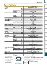
3-phase 4-wire 380-400-415V 50Hz
4.33
2.86
60.0
51,600
204,720
14.2
24.0 - 22.8 - 22.0
4.23
10.3
14.7
45.0
38,700
153,540
10.2
17.2 - 16.4 - 15.8
4.41
7.7
11.2
A++
A++
44
ethylene glycol 35WT% (freezing point -18ºC (-0.4ºF))
14
38
(inlet) less than 55, (outlet) 30~65 *6
(inlet) less than 131, (outlet) 86~149 *6
(inlet) less than 45, (outlet) -8~27
(inlet) less than 113, (outlet) 17.6~80.6
3.2 - 15.0
2.0 - 16.0
50
66
Indoor use only
50.8 (R2") screw
50.8 (R2") screw
50.8 (R2") screw
50.8 (R2") screw
Unpainted steel plate
1,561 × 934 × 780
413 (910)
4.15
1.0
KC94L652X01
KC94L810X01
stainless steel plate and copper brazing
stainless steel plate and copper brazing
Inverter scroll hermetic compressor
MITSUBISHI ELECTRIC CORPORATION
Inverter
0.035 × 2
MEL32
High pres.Sensor & High pres.Switch at 4.15MPa (601psi)
Over-heat protection, Over current protection
Over-heat protection
LEV and HIC circuit
R410A
2,088
9.0
232
Heat source temp 0/-3, Hot water temp 30/35
Heat source temp 0/-3, Hot water temp 47/55
Power input *2
Current input 380-400-415V
COP (kW / kW)
Hot water flow rate
Heat source flow rate
Power input *2
Current input 380-400-415V
COP (kW / kW)
Hot water flow rate
Heat source flow rate
Hot water side *3
Heat source side *3
Hot water side
Heat source side *4
Hot water side
Heat source side *7
Inlet
Outlet
Inlet
Outlet
R410A
Water
Wiring
External
Hot water side
Heat source side
Type
Maker
Starting method
Case heater
Lubricant
High pressure protection
Inverter circuit
Compressor
Weight
CO
2
equivalent
kW
kcal/h
BTU/h
kW
A
m
3
/h
m
3
/h
kW
kcal/h
BTU/h
kW
A
m
3
/h
m
3
/h
A
kPa
kPa
ºC
ºF
ºC
ºF
m
3
/h
m
3
/h
dB (A)
dB (A)
mm (in.)
mm (in.)
mm (in.)
mm (in.)
mm
kg (lbs)
MPa
MPa
kW
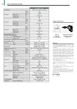
Model
Power Source
SCOP(TDesign60kW):EN14825
Average climate conditions
Capacity1 *1
Capacity2 *1
Seasonal space heating energy efficiency class for medium-temperature application
Seasonal space heating energy efficiency class for low-temperature application
Maximum current input
Heat source fluid type
Water pressure drop
Temp range
Circulating water volume range
Sound pressure level (measured in anechoic room) at 1m *3
Sound power level (measured in anechoic room) *3
Installation location*5
Diameter of water pipe
(hot water side)
Diameter of water pipe
(heat source side)
External finish
External dimension H × W × D
Net weight
Design Pressure
Drawing
Heat exchanger
Compressor
Protection
Control
Type
GWP *8
Original charged
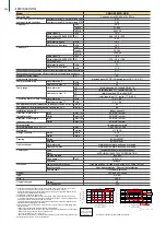
*1 Under Normal heating conditions at outlet hot water temp 35ºC(95ºF) outlet heat source temp
-3ºC(26.6ºF) inlet hot water temp 30ºC(86ºF) inlet heat source temp 0ºC(32ºF).
Heating performance indicates the performance with counter flow of brine and refrigerant at the
heat source HEX. (Standard pipe connection)
*2 Includes pump input based on EN14511.
*3 Under Normal heating conditions at outlet hot water temp 35ºC(95ºF) outlet heat source temp
-3ºC(26.6ºF) inlet hot water temp 30ºC(86ºF) inlet heat source temp 0ºC(32ºF) capacity 60kW hot
water flow rate 10.3m
3
/h heat source flow rate 14.7m
3
/h
Heating performance indicates the performance with counter flow of brine and refrigerant at the
heat source HEX. (Standard pipe connection)
*4 When using in inlet heat source temp is more than 27ºC, please change to parallel piping at the
heat source side.
* Please don't use the steel material for the water piping material.
* Please always make water circulate or pull out the circulation water completely when not using it.
* Please do not use groundwater and well water in direct.
* The water circuit must use the closed circuit.
* Due to continuing improvement, the above specifications may be subject to change without notice.
*5 Install the unit indoors only. Do not install outdoors.
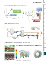
Temp Range
20
30
40
50
60
70
-20
-10
0
10
20
30
40
50
Heat source inlet(ºC)
H
ot
wa
te
r o
ut
le
t(º
C
)
Heat source inlet(ºF)
-4
14
32
50
68
86
104
122
H
ot
wa
te
r o
ut
le
t(º
F)
68
86
104
122
140
158
Counter
Parallel
*6
*7
*8 This table is based on Regulation(EU) No517/2014
kcal/h =kW × 860
BTU/h =kW × 3,412
lbs =kg/0.4536
Unit converter
-20
-10
0
10
20
30
40
50
Heat source inlet (
ºC)
Heat source inlet (
ºF)
-4
14
32
50
68
86
104
122
Counter
Parallel
0
2
4
6
8
10
12
14
16
18
Hea
t s
ource
flow
ra
te
(m
3
/h
)
Flow Range
234
SPECIFICATIONS
Summary of Contents for City Multi R2 Series
Page 1: ...CM20AN E NZ VRF City Multi Product Catalogue ...
Page 101: ...BC Controllers 101 ...
Page 112: ...Indoor Units VRF 112 ...
Page 114: ...Ceiling Cassette Type 4 Way Airflow Type 114 ...
Page 122: ...Ceiling Cassette Type 2 Way Airflow Type 122 ...
Page 128: ...Ceiling Concealed Type 128 ...
Page 150: ...Wall Mounted Type 150 ...
Page 154: ...Floor Standing Type 154 ...
Page 181: ...Ventilation Systems 181 ...
Page 190: ...Remote Controllers 190 ...

