♦Depending on the operating conditions, the unit generates noise caused by valve actuation, refrigerant flow,
and pressure changes even when operating normally. Try to avoid positioning the air conditioner in locations
where quietness is required.
With regard to the BC/HBC controller, it is recommended that the unit be installed in areas such as corridor
ceilings, restrooms and plant rooms.
♦The total capacity of the connected indoor units can be greater than the capacity of the outdoor/heat source
unit.
However, when the connected indoor units operate simultaneously, each unit's capacity may become smaller
than the rated capacity.
♦When the unit is started up for the first time within 12 hours after the power comes on, i.e. after a power failure,
it performs initial startup operation (capacity control operation) to prevent damage to the compressor. The
initial startup operation requires a maximum of 90 minutes to complete, depending on the operating load.
1-5. Related equipment
♦Use an earth leakage breaker (ELB) with medium sensitivity, and an activation speed of 0.1 second or less.
♦Consult your local distributor or a qualified technician when installing an earth leakage breaker.
♦If the unit is an inverter type, select an earth leakage breaker able to respond to high harmonic waves and
surges.
♦Leakage current is generated not only through the air-conditioning unit but also through the power wires. The
leakage current of the main power supply is therefore greater than the total leakage current of each unit. Take
the capacity of the earth leakage breaker or leakage alarm into consideration when installing one at the main
power supply. To measure the leakage current simply on site, use a measurement tool equipped with a filter,
and clamp all the four power wires together. The leakage current measured on the ground wire may not be
accurate because the leakage current from other systems may be included in the measurement value.
♦Do not install a phase-advancing capacitor on a unit connected to the same power system as an inverter-type
unit and its related equipment.
♦If a large current flows due to the malfunctioning of the product or faulty wiring, both the earth leakage breaker
on the product side and the upstream overcurrent breaker may trip almost at the same time. Separate the
power system or coordinate all the breakers depending on the system's priority level.
1-6. Unit installation
♦Your local distributor or a qualified technician must read the Installation Manual that is provided with each unit
carefully before performing installation work.
♦Consult your local distributor or a qualified technician when installing the unit. Improper installation by an
unqualified person may result in water leakage, electric shock, or fire.
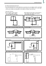
♦Ensure that there is enough space around each unit.
1-7. Optional accessories
♦Only use accessories recommended by Mitsubishi Electric. Consult your local distributor or a qualified
technician when installing them. Improper installation by an unqualified person may result in water leakage,
power leakage, system breakdown, or fire.
♦Some optional accessories may not be compatible for use with the air-conditioning unit or may not be suitable
for the installation conditions. Check the compatibility when considering any accessories.
♦Note that some optional accessories may affect the air conditioner's external form, appearance, weight,
operating sound, and other characteristics.
1-8. Operation/Maintenance
♦Read the Instruction Book that is provided with each unit carefully prior to use.
♦Maintenance or cleaning of each unit may be risky and require expertise. Read the Instruction Book to ensure safety.
Consult your local distributor or a qualified technician when special expertise is required, such as when the
indoor unit needs to be cleaned.
237
Installation Information
Summary of Contents for City Multi R2 Series
Page 1: ...CM20AN E NZ VRF City Multi Product Catalogue ...
Page 101: ...BC Controllers 101 ...
Page 112: ...Indoor Units VRF 112 ...
Page 114: ...Ceiling Cassette Type 4 Way Airflow Type 114 ...
Page 122: ...Ceiling Cassette Type 2 Way Airflow Type 122 ...
Page 128: ...Ceiling Concealed Type 128 ...
Page 150: ...Wall Mounted Type 150 ...
Page 154: ...Floor Standing Type 154 ...
Page 181: ...Ventilation Systems 181 ...
Page 190: ...Remote Controllers 190 ...


