50°
70°
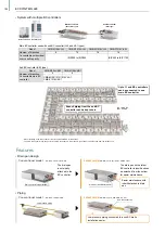
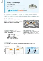
• Corner panel
• Control box cover
No need to remove screws
Temporary hanging hook
• Conventional model
• Latest model
• Conventional model
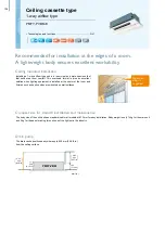
• Horizontal airflow
• Latest model
Increased space for plumbing work
Electrical box wiring
Maximum 4 m
automatic
elevation
1.2 m
1.6 m
2.0 m
2.4 m
2.8 m
3.2 m
3.6 m
4.0 m
• Airflow distribution
Horizontal airflow
PLFY-P80VEM-A
<Cooling mode> Standard
Flow angle: 10° 4-way flow
Ceiling height: 2.7m
Cold air
doesn’t affect
me directly.
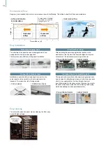
Supply air is horizontally fed into the room to reduce the cold draft feeling. This airflow is ideal for offices and restaurants.
The structure of the panel has been redesigned and is now
equipped with a temporary hanging hook.
This improves work efficiency during panel installation.
Installation is possible without removing the screws for the
corner panel and the control box; they simply need to be
loosened. This lowers the risk of losing screws.
After reviewing the power supply terminal position in the
electrical box, the structure has been redesigned to improve
connectivity. This makes complex wiring work easier.
The top and bottom positions of the liquid and gas pipes have
been reversed to allow the gas pipe work, which requires more
effort, to be completed first. Further, through structural
innovations related to the space around the pipes, the area for
the spanner has been increased, thus improving liquid piping
work and enabling it to be completed smoothly.
The automatic elevation panel makes cleaning the filter easy,
even with high ceilings.
Easy installation
Easy cleaning
0
1
2
3
4
0
1
2
2.7
(m/s)
Floor distance (m)
Height (m)
1
2
3
4
0.5
1.0
1.5
2.0
2.5
0.5
1.0
1.5
2.0
2.5
Horizontal
airflow
Horizontal
airflow
117
VRF
Y-Series
VRF
Lineup
VRF
R2-Series
VRF
Zubadan
VRF
WY-Series
VRF
WR2-Series
VRF
S-Series
VRF
Indoor Units
Ventilation
Systems
Technologies and Functions
Remote Controller
Hot Water Solution
VRF
BC Controllers
VRF
S-Series
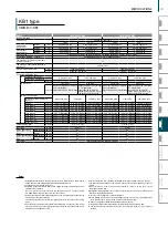
SPECIFICATIONS
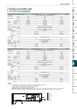
Ceiling cassette type
4-way airfl ow type
PLFY-P VEM-E/A
PLFY-P20VEM-E
PLFY-P25VEM-E
Power source
1-phase 220–240V 50Hz, 1-phase 220V 60Hz
Cooling capacity
(Nominal)
*1
kW
2.2
2.8
*1 BTU/h
7,500
9,600
Power input
kW
0.03
0.03
Current input
A
0.31
0.31
Heating capacity
(Nominal)
*2
kW
2.5
3.2
*2 BTU/h
8,500
10,900
Power input
kW
0.03
0.03
Current input
A
0.24
0.24
External fi nish
Galvanized steel sheet
External dimension
HxWxD
mm
258 x 840 x 840
in.
10-3/16 x 33-3/32 x 33-3/32
Net weight
kg (lbs)
19 (42)
19 (42)
Decoration
panel
model
PLP-6EA
PLP-6EA
External fi nish
MUNSELL (1.0Y 9.2/0.2)
Dimension
H x W x D
mm
40 x 950 x 950
in.
1-9/16 x 37-13/32 x 37-13/32
Net weight
kg (lbs)
5 (11)
Heat exchanger
Cross fi n (Aluminum fi n and copper tube)
FAN
Type x Quantity
Turbo fan x 1
Turbo fan x 1
External
static press.
Pa
0
0
mmH
2
O
0
0
Motor Type
DC motor
Motor output
kW
0.050
0.050
Driving mechanism
Direct-drive
Air fl ow rate
(Low-Mid2-
Mid1-High)
m
3
/min
12 - 13 - 14 - 15
12 - 13 - 14 - 15
L/s
200 - 217 - 233 - 250
200 - 217 - 233 - 250
cfm
424 - 459 - 494 - 530
424 - 459 - 494 - 530
Sound pressure level
(Low-Mid2-Mid1-High)
(measured in anechoic room)
dB<A>
24 - 26 - 27 - 29
24 - 26 - 27 - 29
Air fi lter
PP honeycomb
Refrigerant piping
diameter
Liquid mm (in.)
Ø
6.35 (
Ø
1/4) Flare
Ø
6.35 (
Ø
1/4) Flare
Gas
mm (in.)
Ø
12.7 (
Ø
1/2) Flare
Ø
12.7 (
Ø
1/2) Flare
Field drain pipe size
mm (in.)
O.D.
Ø
32 (1-1/4) (VP-25)
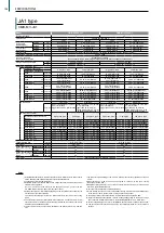
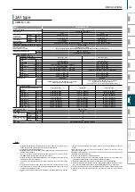
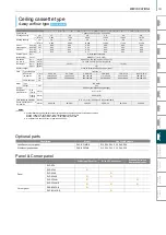
PLFY-P32VEM-A
PLFY-P40VEM-A
PLFY-P50VEM-A
PLFY-P63VEM-A
PLFY-P80VEM-A PLFY-P100VEM-A PLFY-P125VEM-A
Power source
1-phase 220-240V 50Hz, 1-phase 220/230V 60Hz
Cooling capacity
*1
kW
3.6
4.5
5.6
7.1
9.0
11.2
14.0
(Nominal)
*1 kcal / h
3,100
3,900
4,800
6,100
7,700
9,600
12,000
*1 BTU / h
12,300
15,400
19,100
24,200
30,700
38,200
47,800
Power input
kW
0.03
0.03
0.03
0.03
0.05
0.07
0.11
Current input
A
0.32
0.32
0.32
0.36
0.50
0.67
1.06
Heating capacity
*2
kW
4.0
5.0
6.3
8.0
10.0
12.5
16.0
(Nominal )
*2 kcal / h
3,400
4,300
5,400
6,900
8,600
10,800
13,800
*2 BTU / h
13,600
17,100
21,500
27,300
34,100
42,700
54,600
Power input
kW
0.03
0.03
0.03
0.03
0.05
0.07
0.11
Current input
A
0.25
0.25
0.25
0.29
0.43
0.60
0.99
External fi nish
Galvanized steel sheet
External dimension
H x W x D
mm
258 x 840 x 840
258 x 840 x 840
258 x 840 x 840
258 x 840 x 840
258 x 840 x 840
298 x 840 x 840
298 x 840 x 840
in.
10-3/16 x 33-3/32 x 33-3/32 10-3/16 x 33-3/32 x 33-3/32 10-3/16 x 33-3/32 x 33-3/32 10-3/16 x 33-3/32 x 33-3/32 10-3/16 x 33-3/32 x 33-3/32 11-3/4 x 33-3/32 x 33-3/32 11-3/4 x 33-3/32 x 33-3/32
Net weight
kg (lbs)
19 (42)
19 (42)
19 (42)
21 (46)
21 (46)
24 (53)
24(53)
Decoration
panel
Model
PLP-6EA
PLP-6EA
PLP-6EA
PLP-6EA
PLP-6EA
PLP-6EA
PLP-6EA
External fi nish
MUNSELL (1.0Y 9.2/0.2)
Dimension
H x W x D
mm
40 x 950 x 950
in.
1-9/16 x 37-13/32 x 37-13/32
Net weight
kg (lbs)
5 (11)
5 (11)
5 (11)
5 (11)
5 (11)
5 (11)
5 (11)
Heat exchanger
Micro slit fi n (Aluminum fi n and copper tube)
FAN
Type x Quantity
Turbo fan x 1
Turbo fan x 1
Turbo fan x 1
Turbo fan x 1
Turbo fan x 1
Turbo fan x 1
Turbo fan x 1
External
static press.
Pa
0
0
0
0
0
0
0
mmH
2
O
0
0
0
0
0
0
0
Motor type
DC motor
Motor output
kW
0.050
0.050
0.050
0.050
0.050
0.120
0.120
Driving mechanism
Direct-drive
Airfl ow rate
(Low-Mid2-
Mid1-High)
m
3
/ min
13 - 14 - 16 - 17
13 - 14 - 16 - 18
13 - 14 - 16 - 19
15 - 16 - 17 - 19
15 - 18 - 20 - 23
20 - 23 - 26 - 29
24 - 26 - 30 - 35
L / s
217 - 233 - 267 - 283 217 - 233 - 267 - 300 217 - 233 - 267 - 317 250 - 267 - 283 - 317 250 - 300 - 333- 383 333 - 383 - 433 - 483 400 - 433 - 500 - 583
cfm
459 - 494 - 565 - 600 459 - 494 - 565 - 636 459 - 494 - 565 - 671 530 - 565 - 600 - 671 530 - 636 - 706 - 812 706 - 812 - 918 - 1024 847 - 918 - 1060 - 1236
Sound pressure level
(Low-Mid2-Mid1-High)
(measured in anechoic room)
dB <A>
26 - 27 - 29 - 31
26 - 27 - 29 - 31
26 - 27 - 29 - 31
28 - 29 - 30 - 32
28 - 31 - 34 - 37
34 - 37 - 39 - 41
35 - 39 - 42 - 45
Air fi lter
PP honeycomb
Refrigerant control device
LEV
Diameter of
refrigerant pipe
Liquid (R410A) mm (in.) ø6.35 (ø1/4) Flare ø6.35 (ø1/4) Flare ø6.35 (ø1/4) Flare ø9.52 (ø3/8) Flare ø9.52 (ø3/8) Flare ø9.52 (ø3/8) Flare ø9.52 (ø3/8) Flare
Gas (R410A) mm (in.) ø12.7 (ø1/2) Flare ø12.7 (ø1/2) Flare ø12.7 (ø1/2) Flare ø15.88 (ø5/8) Flare ø15.88 (ø5/8) Flare ø15.88 (ø5/8) Flare ø15.88 (ø5/8) Flare
Field drain pipe size
mm (in.)
O.D. ø32 (1-1/4) (VP-25)
*1 Nominal cooling conditions
Indoor: 27°CDB/19°CWB (81°FDB/66°FWB), Outdoor: 35°CDB (95°FDB)
Pipe length: 7.5m (24-9/16ft.), Level diff erence: 0m (0ft.)
*2 Nominal heating conditions
Indoor: 20°CDB (68°FDB), Outdoor: 7°CDB/6°CWB (45°FDB/43°FWB)
Pipe length: 7.5m (24-9/16ft.), Level diff erence: 0m (0ft.)
*3 Nominal conditions *1 and *2 are subject to JIS B8615-1.
*4 Due to continuing improvement, above specifi cation may be subject to change without notice.
Notes:
Summary of Contents for City Multi R2 Series
Page 1: ...CM20AN E NZ VRF City Multi Product Catalogue ...
Page 101: ...BC Controllers 101 ...
Page 112: ...Indoor Units VRF 112 ...
Page 114: ...Ceiling Cassette Type 4 Way Airflow Type 114 ...
Page 122: ...Ceiling Cassette Type 2 Way Airflow Type 122 ...
Page 128: ...Ceiling Concealed Type 128 ...
Page 150: ...Wall Mounted Type 150 ...
Page 154: ...Floor Standing Type 154 ...
Page 181: ...Ventilation Systems 181 ...
Page 190: ...Remote Controllers 190 ...


