


4. PARAMETERS FOR POSITIONING CONTROL
4
−
14
4.3.4
Speed integral compensation
(1) This parameter is used to increase frequency response in speed control and
improve transient characteristics.
(2) If the overshoot in acceleration/deceleration cannot be made smaller by
adjusting speed loop gain or speed control gain, increasing the setting for the
speed integral compensation value will be effective.
(3) A guide to setting the speed integral compensation is presented in Table 4.6
below.
Table 4.6 Guide to Speed Integral Compensation Setting
Load Inertia Ratio
(GD
L
2
/GD
M
2
)
1
3
5
10
20
30 or
Greater
Remarks
Set value (ms)
20
30
40
60
100
200
Setting possible within the range 1 to 9999
(valid range: 1 to 1000)
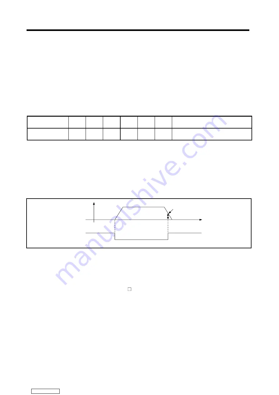
4.3.5 In-position
range
(1) The "in-position" refers to the quantity of droop pulses in the deviation counter.
(2) If an in-position value is set, the in-position signal (M1602
+
20n) will come ON
when the difference between the position command and position feedback from
the servomotor enters the set range.
In-position signal
(M16m2)
Set value for in-position range
t
OFF
ON
Amount of
droop
4.3.6
Feed forward gain
This parameter is used to improve the follow-up of the servo system.
The setting range is as follows:
When using an MR- -B...................0 to 100 (%)
Downloaded from


