


8. AUXILIARY AND APPLIED FUNCTIONS
8
−
3
(2) Limit Switch Enable/Disable Setting
The following devices can be used to enable or disable the limit switch output
from each axis or each point.
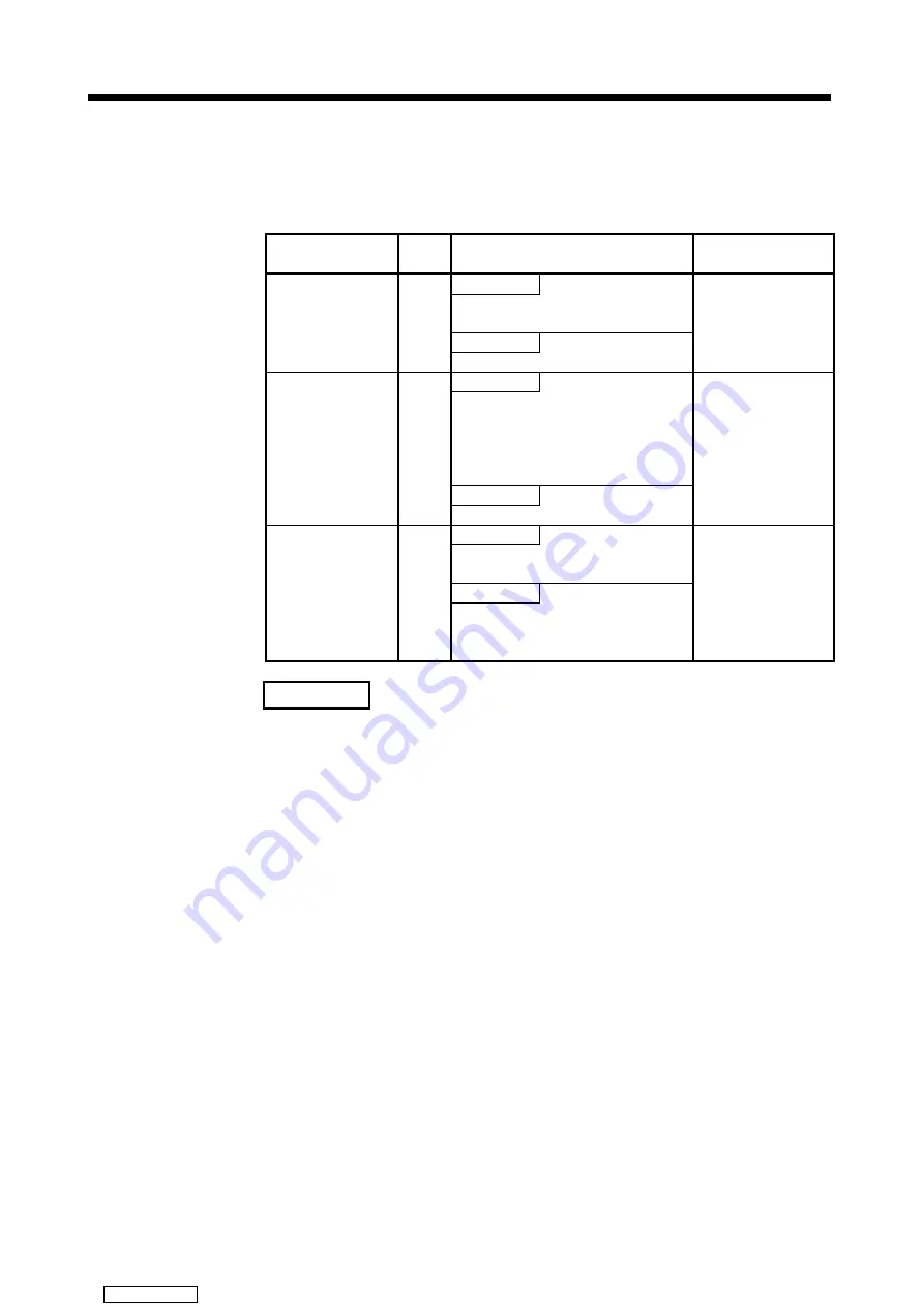
Table 8.1 Limit Switch Enable/Disable Settings
Set Data/Device
Setting
Unit
Processing
Set Data Valid Timing
Used
Set ON/OFF pattern can be output for the
appropriate axis.
Not Used
Limit switch output
used/not used setting
in the fixed
parameters.
Axis
All outputs OFF for the appropriate axis.
(1) Leading edge of
PLC ready (M2000)
(2) When test mode is
started
ON
ON/OFF pattern is output for the
appropriate axis based on the set
ON/OFF pattern and the limit switch
output disable setting registers (D1008
and D1009).
OFF
Limit switch output
enable signal
(M1806
+
20n)
Axis
All outputs OFF for the appropriate axis.
Limit switch output
used/not used setting in
the fixed parameters is
set to "used."
Disable bit (1)
Outputs corresponding to disable bits set
to "1" are OFF.
Enable bit (0)
Limit switch output
disable setting
registers
(D1008 and D1009)
Point
Outputs corresponding to enable bits set
to "0" output an ON/OFF pattern based on
the set ON/OFF pattern.
While M1806
+
20n is
ON.
REMARK
The data in Table 8.1 is also valid during the test mode set by a peripheral
device.
(3) Cautions
(a) The limit switch output is based on the "feed current value" for each axis
after PLC ready (M2000) turns ON and the PCPU ready flag (M9074) is ON.
All points turn OFF when the PCPU ready flag (M9074) turns OFF.
(b) While the PCPU ready flag (M9074) is ON and the feed current value is
outside the set stroke limits, the limit switch output is based on M1806
+
20n.
Consequently, the user should apply an interlock to ensure that the
sequence program turns M1806
+
20n ON inside the stroke limit range only.
Downloaded from


