background image

20.1  GOT Restoration Sheet

20

 - 11

17

ADDI

TIO

N

 TIMES 

RE

SET FOR 

MA

INTENA

N

C

E


18

INST

ALL

A

TI

ON OF 

B

O

OT

O

S

 A

ND 

ST

A

N

DA

RD OS

19

MAIN

TE

NANCE A

ND 

INSP

ECTIO

N

20

ERROR MESS

AGE


AND SYSTE

M


ALA

R

M

AP

PENDI

C

E

S

IND

E

X

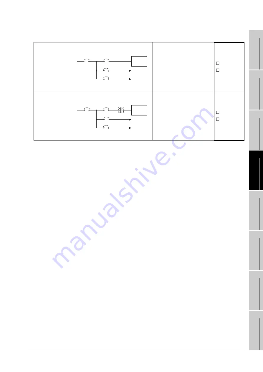
(7) Power supply system

Current status

The power from the same 
system is used for the GOT, I/O 
equipment (such as relay), and 
power equipment (such as servo 
amplifier).

 Used

 Not used

Measure for the 
equipment for 
which the power 
from the same 
system is used

Connecting an isolation 
transformer as well as 
separating the wiring of the GOT 
power from that of the power of 
the I/O equipment and power 
equipment reduces the influence 
of noise.

 Effective

 Ineffective

Main power

PLC power

AC200V

I/O power

Main circuit power

I/O 

equipment

Power 

equipment

PLC

GOT

Main power

PLC power

Isolation transformer

AC200V

I/O power

Main circuit power

I/O 

equipment

Power 

equipment

PLC

GOT

Summary of Contents for GOT1000

Page 1: ......

Page 2: ......

Page 3: ...nction If a communication fault including cable disconnection occurs during monitoring on the GOT communication between the GOT and PLC CPU is suspended and the GOT becomes inoperative For bus connect...

Page 4: ...o not touch the display section in 2 points or more simultaneously Doing so may cause an accident due to incorrect output or malfunction CAUTION Do not bundle the control and communication cables with...

Page 5: ...age of the screws or unit When mounting the multi color display board onto the GOT tighten the mounting screws within the specified torque range Loose tightening may cause the unit and or GOT to malfu...

Page 6: ...s of the GOT power supply section in the specified torque range Undertightening can cause a short circuit or malfunction Overtightening can cause a short circuit or malfunction due to the damage of th...

Page 7: ...the system False output or malfunction can cause an accident DANGER When power is on do not touch the terminals Doing so can cause an electric shock or malfunction Connect the battery correctly Do not...

Page 8: ...tion fault Do not drop the module or subject it to strong shock A module damage may result Do not drop or give an impact to the battery mounted to the unit Doing so may damage the battery causing the...

Page 9: ...a burn from heat of the backlight CAUTION When disposing of the product handle it as industrial waste CAUTION When transporting lithium batteries make sure to treat them based on the transport regulat...

Page 10: ...on 2 1 2 2 2 2 1 2 2 2 Section 4 1 to 4 4 Section 5 1 5 1 3 5 2 5 5 4 2 Section 6 3 Section 7 7 4 Section 8 1 8 1 1 8 1 2 8 2 8 3 8 5 1 8 5 2 8 6 2 8 7 3 8 7 4 8 11 8 11 1 Section 9 9 1 9 2 9 3 1 to 9...

Page 11: ...8 10 8 11 8 12 8 13 9 2 9 3 1 10 1 3 Chapter 11 Section 11 1 1 11 1 2 11 5 1 11 7 1 11 8 1 Chapter 14 Section 14 1 1 14 2 1 19 6 1 20 2 Appendix 1 3 5 Section 3 2 5 4 5 5 3 4 8 6 11 9 11 11 13 11 14...

Page 12: ...3 2 3 3 2 5 3 3 5 4 1 6 3 7 2 8 5 8 7 8 6 8 8 8 7 8 9 8 8 8 10 8 9 8 11 8 10 8 12 8 11 8 13 8 12 8 14 8 16 1 9 2 10 1 3 10 2 3 11 7 1 11 7 2 11 7 3 13 5 2 13 5 3 14 1 1 14 1 2 14 7 20 3 2 Appendix 3 6...

Page 13: ...95 X 3 2 3 2 2 GT1585V S GT1585 S 3 5 3 2 3 GT1575V S GT1575 S GT1575 V GT1575 VN GT1572 VN 3 7 3 2 4 GT1565 V GT1562 VN 3 10 3 2 5 GT1555 V GT1555 Q GT1550 Q 3 12 3 3 Power Supply Specifications 3 14...

Page 14: ...ion is used 5 13 5 3 6 Cables 5 14 5 4 Precautions for Wiring Connecting the EMC Directive Compliant Product 5 15 5 4 1 Power and ground wires wiring method 5 15 5 4 2 Processing connection cables 5 1...

Page 15: ...Installation procedure 8 28 8 7 CF Card Unit and CF Card Extension Unit 8 31 8 7 1 Applicable CF card unit and CF card extension unit 8 31 8 7 2 Installing on GOT 8 31 8 7 3 Installing on control pan...

Page 16: ...SETTING COMMUNICATION SETTING 10 1 to 10 16 10 1 Communication Setting 10 1 10 1 1 Communication setting functions 10 1 10 1 2 Communication setting display operation 10 1 10 1 3 Communication settin...

Page 17: ...t Settings Transparent Mode Setting 11 29 11 8 1 Function of the transparent mode 11 29 11 8 2 Displaying the transparent mode 11 29 11 8 3 Operation the transparent mode 11 30 11 9 Video Unit Setting...

Page 18: ...nformation 13 26 13 4 3 The display example of alarm information 13 27 13 4 4 Alarm information operation 13 28 13 5 Hard Copy Information 13 34 13 5 1 The function of hardcopy information 13 34 13 5...

Page 19: ...example of GOT data package acquisition 13 108 13 12 4 GOT data package acquisition operation 13 109 14 GOT SELF CHECK DEBUG SELF CHECK 14 1 to 14 48 14 1 Debug 14 1 14 1 1 The Debug function 14 1 14...

Page 20: ...ing 16 2 16 1 1 Function of the maintenance timing setting 16 2 16 1 2 Display operation of maintenance timimg setting 16 3 16 1 3 Operating the maintenance timing setting 16 4 17 ADDITION TIMES RESET...

Page 21: ...or positions 20 15 20 2 3 Specific example of troubleshooting 20 16 20 3 ERROR MESSAGE AND SYSTEM ALARM 20 17 20 3 1 Error Contents Display 20 17 20 3 2 List of Error Message System Alarm 20 19 APPEND...

Page 22: ...For GOT1000 Series 2 3 GT Designer2 Version2 Screen Design Manual For GOT1000 Series 3 3 Describes specifications and settings of the object functions used in GOT1000 series Sold separately 1 SH 0805...

Page 23: ...GT1585 GT157 GT156 GT155 GT115 GT1155 Q Abbreviation of GT1155 QTBDQ GT1155 QSBDQ GT1155 QTBDA GT1155 QSBDA GT1155 QSBD GT1150 Q Abbreviation of GT1150 QLBDQ GT1150 QLBDA GT1150 QLBD Handy GOT GT1155H...

Page 24: ...GT10 30PSCW GT10 30PSGW GT10 20PSCB GT10 20PSGB GT10 20PSCW GT10 20PSGW USB environmental protection cover GT15 UCOV GT11 50UCOV Stand GT15 90STAND GT15 80STAND GT15 70STAND A9GT 50STAND GT05 50STAND...

Page 25: ...ufactured by YASKAWA Electric Corporation Yokogawa PLC Abbreviation of PLC manufactured by Yokogawa Electric Corporation Allen Bradley PLC Abbreviation of PLC manufactured by Allen Bradley SIEMENS PLC...

Page 26: ...are used in this manual The above is different from the actual page as it is provided for explanation only Refers to the information required Refers to the supplementary explanations for reference Ind...

Page 27: ...005 GT1575 S Hardware Version B or earlier Apr 2005 GT1575 V Hardware Version D or earlier Apr 2005 GT1565 V Hardware Version D or earlier Apr 2005 Model Description Quantity GT1595 X GOT 1 Installati...

Page 28: ...d Numeric display can be laid out arbitrarily to be displayed Moreover the multiple screens created by GT Designer2 can be overlapped and switched to be displayed For details refer to the following GT...

Page 29: ...Drawing Data transfer For operations from creating project data to transferring data to GOT refer to the following manuals 1 Stored in the GT Works2 GT Designer2 in PDF format Purpose GT Designer2 Ve...

Page 30: ...how to use the GT SoftGOT1000 and various functions d GT Simulator2 Version Operating Manual Describes how to simulate the created project data with the GT Simulator2 e GT Converter2 Version Operating...

Page 31: ...is included as standard Font installation is available to increase the system fonts Combined use of 4 types of alarms system alarm user alarm alarm history alarm popup display realizes more efficient...

Page 32: ...o the GOT After installation is completed the GOT automatically restarts 2 Download the project data created by the PC 1 Write the OS program project data installed in the PC in the memory card 1 Writ...

Page 33: ...The overall configuration of GOT is as follows For the connection methods applicable to GOT1000 series and cable refer to the following GOT1000 Series Connection Manual Option function board CF card...

Page 34: ...T TFT color High intensity Wide angle view N TFT color S STN color L STN monochrome V Video RGB compliant None 5 65536 4096 256 colors 1 2 16 colors 0 Monochrome White Black 16 gray scale 2 9 15 8 12...

Page 35: ...SL GT15 75ABUS2L can also be used with GT155 2 The USB environmental protection cover GT11 50UCOV can be used for both the GT15 and GT11 None Common for all types 90 Dedicated for 15 80 Dedicated for...

Page 36: ...are different such as servo inverter temperature controller Cable distinction numbers for one manufacturer s products Two digit sequence number 01 02 When cable distinction is needed for one manufact...

Page 37: ...0 dots TFT color liquid crystal high intensity wide angle view 65536 colors 1 video RGB compliant 100 to 240VAC memory size 9MB GT1575V STBD 10 4 800 600 dots TFT color liquid crystal display high int...

Page 38: ...olors 100 to 240VAC Memory size 5MB GT1562 VNBD 8 4 640 480 dots TFT color liquid crystal 16 colors 24VDC Memory size 5MB GT1555 VTBD 5 7 640 480 dots TFT color liquid crystal high intensity wide angl...

Page 39: ...GT15 75ABUS2L For intermediary and terminal GOTs 2 channels Serial communication unit GT15 RS2 For RS 232 interface connection connector type GT15 RS4 For RS 422 interface connection connector type GT...

Page 40: ...B GT15 A1SC07NB Cable length 0 7m GT15 A1SC30NB Cable length 3m GT15 A1SC50NB Cable length 5m For connecting QnAS AnSCPU and A7GT CNB Large size CPU extension cable GT15 C12NB Cable length 1 2m For co...

Page 41: ...ame Model name Description RS 232 cable QCPU direct connection cable GT01 C30R2 6P Cable length 3m For connecting QCPU and GOT FX communication function extension board connection cable FX communicati...

Page 42: ...T01 C300R4 25P Cable length 30m Computer link connection cable GT09 C30R4 6C Cable length 3 m For connecting computer link module serial communication module and GOT GT09 C100R4 6C Cable length 10 m G...

Page 43: ...uct name Model name Description RS 232 cable GT09 C30R20601 15P Cable length 3m For connecting GOT to SHARP PLC GT09 C30R20602 15P Cable length 3m For connecting GOT to SHARP PLC RS 422 cable GT09 C30...

Page 44: ...BA PLC GT09 C100R40503 15P Cable length 10m GT09 C200R40503 15P Cable length 20m GT09 C300R40503 15P Cable length 30m Product name Model name Description RS 232 cable GT09 C30R20401 15P Cable length 3...

Page 45: ...gth 20m GT09 C300R40201 9P Cable length 30m GT09 C30R40202 14P Cable length 3m For connecting GOT to YASKAWA PLC GT09 C100R40202 14P Cable length 10m GT09 C200R40202 14P Cable length 20m GT09 C300R402...

Page 46: ...n products MELFANSweb home page MELFANSweb website http wwwf2 mitsubishielectric co jp english index html Memory card adaptor Sold separately Product name Model name Description RS 422 conversion unit...

Page 47: ...48M Option function board with add on memory Option function 48MB Applicable for MELSEC Q QnA A FX ladder monitor function multi channel function GT15 MESB48M Option function board with add on memory...

Page 48: ...del name Description Protective sheet GT15 90PSCB 15 protective sheet Clear 5 sheets GT15 90PSGB Antiglare 5 sheets GT15 90PSCW Clear Frame white 5 sheets GT15 90PSGW Antiglare Frame white 5 sheets GT...

Page 49: ...or later GT15 70VLTN For 10 4 TFT VGA GT1575 VN GT1572 VN GT15 60VLTT For 8 4 high intensity wide angle view TFT VGA GT1565 V GT15 60VLTN For 8 4 TFT VGA GT1562 VN Product name Model name Description...

Page 50: ...e voltage withstand level for up to the raged voltage of 300 V is 2500 V 5 This index indicates the degree to which conductive material is generated in the environment where the equipment is used In p...

Page 51: ...ers 48 lines 2byte character 12 dot standard font 85 characters 64 lines 2byte character Display color 65536 colors 2 Display angle Left Right 75 degrees Top 50 degrees Bottom 60 degrees Intensity of...

Page 52: ...time notification data Life Approx 5 years Operating ambiant temperature of 25 C Built in interface RS 232 6 RS 232 1ch Transmission speed 115 200 57 600 38 400 19 200 9 600 4 800 bps Connector shape...

Page 53: ...nterface only when a USB cable is connected Note that this does not guarantee all users operation environment 6 When using multiple extension units and a bar code reader the total current of the exten...

Page 54: ...fluorescent tube replaceable backlight shutoff detection function is included Backlight off screen saving time can be set Life 3 Approx 50 000 h or longer Time when display luminance reaches 50 at the...

Page 55: ...r than the total current that the GOT can supply For current values of extension units and bar code reader and the total current that the GOT can supply refer to the following manual GT Designer2 Vers...

Page 56: ...VN 256color GT1572 VN 16color Display angle Left Right Top Bottom 85 degrees Left Right Top Bottom 85 degrees Left Right 45 degrees Top 30 degrees Bottom 20 degrees Intensity of LCD only 400 cd m2 38...

Page 57: ...nsmission speed 115 200 57 600 38 400 19 200 9 600 4 800 bps Connector shape D sub 9 pin Male Application For communicating with a controller or connecting a personal computer Project data upload down...

Page 58: ...environmental protection cover is attached Compliant with IP2X at the USB interface only when a USB cable is connected Note that this does not guarantee all users operation environment 6 When using mu...

Page 59: ...sity adjustment 8 level adjustment 4 level adjustment Life Approx 41 000 h Operating ambient temperature 25 C Backlight Cold cathode fluorescent tube replaceable backlight shutoff detection function i...

Page 60: ...total current that the GOT can supply refer to the following manual GT Designer2 Version Screen Design Manual 2 8 Multi channel Function Item Specifications GT1565 VTBA GT1565 VTBD GT1562 VNBA GT1562...

Page 61: ...70 degrees Top 70 degrees Bottom 50 degrees Left Right 55 degrees Top 65 degrees Bottom 70 degrees Left Right 45 degrees Top 20 degrees Bottom 40 degrees Intensity of LCD only 350 cd m2 400 cd m2 380...

Page 62: ...switches can be certainly operated Use a stylus pen that satisfies the following specifications Material Polyacetal resin Pen tip radius 0 8mm or more Item Specifications GT1555 VTBD GT1555 QTBD GT15...

Page 63: ...TBA GT1575V STBA GT1575 STBA GT1575 VTBA GT1575 VNBA GT1572 VNBA GT1565 VTBA GT1562 VNBA Input power supply voltage 100 to 240VAC 10 15 Input frequency 50 60Hz 5 Input max apparent power 110VA maximum...

Page 64: ...24VDC 30W or less 1250mA 24VDC 14W or less 580mA 24VDC 13W or less 540mA 24VDC Inrush current 100A or less 4ms maximum load 115A or less 1ms maximum load 67A or less 1ms maxim um load 60A or less 1ms...

Page 65: ...W 2 SYSTEM CONFIGURATION 3 SPECIFICATIONS 4 PART NAME AND SETTINGS 5 EMC AND LOW VOLTAGE DIRECTIVE 6 INSTALLATION 7 WIRING 8 OPTION 4 PART NAME AND SETTINGS 4 1 Part Names and Settings of the GT1595 2...

Page 66: ...nal LG terminal FG terminal 7 Extension unit interface For installing an extension unit 8 CF card interface For installing a CF card 9 CF card access LED Lit CF card accessed Not lit CF card not acces...

Page 67: ...4 3 1 OVERVIEW 2 SYSTEM CONFIGURATION 3 SPECIFICATIONS 4 PART NAME AND SETTINGS 5 EMC AND LOW VOLTAGE DIRECTIVE 6 INSTALLATION 7 WIRING 8 OPTION 4 2 Part Names and Settings of the GT1585 2 3 1 17 5 6...

Page 68: ...ng a personal computer Connector type D sub 9 pin 7 Power terminal Power input terminal LG terminal FG terminal 8 Extension unit interface For installing an extension unit 9 CF card interface For inst...

Page 69: ...e RS 232 interface of GT1585 is as follows GOT model name Hardware version Connector GT1585V STBA A March 2006 or later Manufacturer DDK Ltd Model name 17LE 23090 27 D4CK or equivalent product GT1585V...

Page 70: ...4 6 4 3 Part Names and Settings of the GT157 4 3 Part Names and Settings of the GT157 2 3 1 5 6 7 15 16 9 10 8 4 11 14 12 13 GOT rear face...

Page 71: ...face For communicating with a controller or connecting a personal computer Connector type D sub 9 pin 7 Power terminal Power input terminal LG terminal FG terminal 8 Extension unit interface For insta...

Page 72: ...nufacturer Honda Tsushin Kogyo Co Ltd Model name GM C9RMDU11 or equivalent product C April 2005 or later Manufacturer DDK Ltd Model name 17LE 23090 27 D4CK or equivalent product GT1575 STBD A July 200...

Page 73: ...56 4 9 1 OVERVIEW 2 SYSTEM CONFIGURATION 3 SPECIFICATIONS 4 PART NAME AND SETTINGS 5 EMC AND LOW VOLTAGE DIRECTIVE 6 INSTALLATION 7 WIRING 8 OPTION 4 4 Part Names and Settings of the GT156 2 3 1 4 5 6...

Page 74: ...r input terminal LG terminal FG terminal 7 Extension unit interface For installing an extension unit 8 CF card interface For installing a CF card 9 CF card access LED Lit CF card accessed Not lit CF c...

Page 75: ...5 4 11 1 OVERVIEW 2 SYSTEM CONFIGURATION 3 SPECIFICATIONS 4 PART NAME AND SETTINGS 5 EMC AND LOW VOLTAGE DIRECTIVE 6 INSTALLATION 7 WIRING 8 OPTION 4 5 Part Names and Settings of the GT155 1 2 3 4 13...

Page 76: ...9 pin 6 Power terminal Power input terminal FG terminal 7 Extension unit interface For installing an extension unit 8 CF card interface For installing a CF card 9 CF card access LED Lit CF card acces...

Page 77: ...E mark on their products 5 1 Requirements to Meet EMC Directive EMC Directives are those which require any strong electromagnetic force is not output to the external Emission electromagnetic interfere...

Page 78: ...Immunity test in which field is irradiated to the product 80 1000MHz 10V m 1 4 2GHz 10V m 80 AM modulation 1kHz EN61000 4 4 Fast transient burst noise 1 Immunity test in which burst noise is applied t...

Page 79: ...B V m 10m in measurement range 230M 1000MHz QP 47dB V m 10m in measurement range Applied standard Test standard Test details Standard value EN61131 2 2003 Radiated RF immunity Test for checking normal...

Page 80: ...anel and its door is small as possible Attach some EMI gaskets to fill up the space and suppress the leakage of radio waves Out test have been carried out on a panel having the damping characteristics...

Page 81: ...the following filters is recommended The precautions required when installing a noise filter are described below 1 Do not install the input and output cables of the noise filter together to prevent th...

Page 82: ...guaranteed Each manufacturer who fabricates such device should make the final judgement about the application method of the Low Voltage Directive and the product compatibility 5 2 1 Standard subject...

Page 83: ...ection may lower the insulation withstand voltage resulting in insulation destruction The insulation in the GOT is designed to cope with the pollution level 2 so use in an environment with pollustion...

Page 84: ...ct a model which complies with the Low Voltage Directive s requirements for isolation between the primary and secondary circuits 2 Insulation requirements Dielectric withstand voltages are shown in th...

Page 85: ...Hardware version of the GOT Production year and month GT1595 GT1595 XTBA Version B or later Jan 2006 GT1595 XTBD Version B or later Jun 2006 GT1585 GT1585V STBA Version K or later Feb 2007 GT1585V STB...

Page 86: ...meet the EMC Directive specifications for the connected device 5 4 2 8 PLC manufactured by other company microcomputer temperature controller inverter servo amplifier or CNC connection Connected devic...

Page 87: ...005 GT15 75QBUSL GT15 75QBUS2L GT15 75ABUSL GT15 75ABUS2L Version G or later Mar 2005 Direct connection to CPU GOT RS 232 interface GT15 RS2T4 9P Version A or later GT15 RS2 9P GT15 RS4 9S Version D o...

Page 88: ...D or later Jan 2006 Inverter connection GT15 RS2T4 9P Version A or later GT15 RS4 9S Version D or later Jan 2006 Servo amplifier connection GOT RS 232 interface GT15 RS2T4 9P Version A or later GT15...

Page 89: ...e of option Compliant with EMC Directive Not compliant with EMC Directive Product name Model name EMC Directive Hardware version Production year and month Printer unit GT15 PRN Version B or later Feb...

Page 90: ...llowing manuals GT15 MELSECNET H communication unit User s Manual MODEL GT15V 75V4R1 Video RGB Input Unit MODEL GT15V 75V4 Video Input Unit MODEL GT15V 75R1 RGB Input Unit User s Manual b For details...

Page 91: ...llowing instructions the system may not comply with EMC directives 5 4 1 Power and ground wires wiring method 1 Power and ground wires wiring method Connect the power wire and connection cable as show...

Page 92: ...supply section b 24VDC GOT power section GT1595 GT1585 GT157 and GT156 GT155 Be sure to ground the protective ground terminal and the FG terminal respectively 90mm or less Ferrite core ZCAT3035 1330...

Page 93: ...ble a For GT15 QC B GT15 QC BS Peel the sheath with the length shown below at both ends of the cable and expose the shield braided wire for grounding For grounding with cable clamps refer to Section 5...

Page 94: ...re 2 CPU direct connection and computer link connection Peel the sheath with the length shown below of the cable to expose the shield braided wire for grounding For grounding with cable clamps refer t...

Page 95: ...e cable is not required 4 CC Link connection Intelligent device station Strip the outer insulation layer at both ends of the cable by the length shown below to expose the braided shield for grounding...

Page 96: ...nal I O device connection Strip the outer insulation layer at both ends of the cable by the length shown below to expose the braided shield for grounding For grounding with cable clamps Refer to Secti...

Page 97: ...computer temperature controller inverter servo amplifier or CNC connection Produce the cable RS 232 cable RS 422 485 cable for connecting the GOT to a controller with reference to the GOT1000 Series C...

Page 98: ...e the shield braided wire for grounding For grounding with cable clamps refer to Section 5 4 3 b For RS 232 cable Use a twisted pair style for each signal wire except SG FG with SG Peel the sheath wit...

Page 99: ...base unit are installed Braided shield Cable clamps GOT FG terminal FG wire Bus connection cable 1 Ground the braided shield portion of the cable to the control panel with the cable clamp AD75CK b Fo...

Page 100: ...n this manual Do not expose the GOT to dust lamp soot conductive dust corrosive gas or combustible gas high temperature condensing wind or rain or to vibrations and impact Failure to do so can cause a...

Page 101: ...ensions when installing CF card extension unit Make a installation hole on the control panel with the dimensions shown below Make space of 10mm on the left and right of the hole respectively for the i...

Page 102: ...3 6 3 Mounting Position 6 3 Mounting Position 1 For installing GOT When mounting the GOT the following clearances must be left from the other device B A C D E Panel thickness 2 to 4mm 0 08 to 0 16inc...

Page 103: ...79 or more 50 1 97 or more 40 1 58 or more MELSECNET 10 communication unit coaxial is fitted 50 1 97 or more 20 0 79 or more CC Link communication unit GT15 75J61BT13 Z fitted 50 1 97 or more 20 0 79...

Page 104: ...n in such a case The required lead in allowance for cables may be larger than the size of A above depending on the unit or cable used For the lead in allowance for cables at the bottom of the GOT refe...

Page 105: ...ol panel side installation unit is installed on the control panel a distance of 25mm is required around the unit Keep a distance of 25mm or more between the control panel side installation unit and th...

Page 106: ...n the other extension units are used the control panel side installation unit cannot be installed in the areas shown in the following figure Hole for installing GOT Prohibited area for installation wi...

Page 107: ...rnet communication unit GT15 J71E71 100 MELSECNET H communication unit GT15 J71LP23 25 85 GT15 J71BR13 MELSECNET 10 communication unit GT15 75J71LP23 Z 85 GT15 75J71BR13 Z CC Link communication unit G...

Page 108: ...gure X 80 100 40 68 Hole for installing GOT Prohibited area for installation with an extension unit 3 15 1 57 3 94 2 68 Prohibited area for installation with CF card interface A drive Extension unit M...

Page 109: ...rated earlier if it is used at the mounting angle other than the above Therefore the temperature inside the control panel should be within 40 C When mounting an extension unit on the upper stage of ME...

Page 110: ...range of 0 36 to 0 48N m Failure to do so may distort the panel and make a surface waviness on the protective sheet 3 A protection film is attached on the display section of GOT prior to shipment Remo...

Page 111: ...make sure to ground FG terminal and LG terminal of the GOT power supply section by applying Class D Grounding Class 3 Grounding Method or higher which is used exclusively for the GOT Not doing so may...

Page 112: ...cable or a high power drive circuit b Shield the signal lines 2 Reducing generated noise a Use a noise filter etc to reduce the level of the noise generated due to a source such as a high power motor...

Page 113: ...and securely tighten them with a tightening torque of 0 5 to 0 8N m so that no problem will result Separate the 100V AC 200V AC or 24V DC cable from the main circuit lines high voltage large current...

Page 114: ...power cables and ground cables to the power terminals situated on the back of the GOT AC LG FG LG FG INPUT 100 240VAC GOT GOT INPUT 24VDC AD DC Fuse 100 110V AC 24V DC In the case of 100V AC FG GOT I...

Page 115: ...erwise the system becomes susceptible to noise Since the LG terminal has potential equal to a half of the input voltage touching the terminal may lead to an electric shock When grounding the GT155 gro...

Page 116: ...able at a point as close to the GOT as possible to make the ground cable short 2 Grounding examples 1 Independent grounding Best For the control equipment ground the system at one end Especially for t...

Page 117: ...3 Common grounding Not allowed Do not connect the ground cables of the power equipment and control equipment with a wire If the cables are connected noise from the power equipment may influence the c...

Page 118: ...minal shape Applicable solderless terminal RAV1 25 3 V2 S3 3 V2 N3A FV2 N3A Terminal screw Solderless terminal Terminal screw 6 2mm or less 3 2 3 2 6 2mm or less When wiring one cable to one terminal...

Page 119: ...of the GOT are installed together the GOT may malfunction due to noise Separating the ground cable and power line of the GOT in wiring reduces the influence of noise 2 Leading of the ground cable fro...

Page 120: ...the influence of noise may be reduced with the following measure example 2 Measure example 2 Refer to the measure examples 2 1 and 2 2 below When the noise generated from the panel affects the GOT ev...

Page 121: ...ication cable outside the panel open cable holes at two separate places to lead the cables separately out If cables are led out through the same cable hole for wiring reasons the cables are more easil...

Page 122: ...apart from the load If the ground cable or communication cable has to be installed close to the load unavoidably attaching a surge suppressor is effective Attach the surge suppressor at the position...

Page 123: ...nt or I O signal lines 1 When connecting QCPU or motion controller CPU Q series to the GOT Grounding of the FG cable for QCPU and motion controller CPU Q series is not necessary since they have no FG...

Page 124: ...nit power and ground them with a cable 2 Use the GT15 C BS s FG cable of 28cm or less 3 Do not connect the GT15 EXCNB s FG ground cable 4 Connect the GT15 C BS s FG cable on the GOT side to FG of the...

Page 125: ...cable together with the main circuit lines high voltage large current and I O signal lines 2 GOT terminal block The terminal block layout of a GOT differs depending on the model Before wiring check t...

Page 126: ...s power and connect the GOT s ground cable to the protective ground terminal For connecting the ground cables each flat side of the two solderless terminals must be faced 3 For the ground cable of the...

Page 127: ...s GT15 ABUS 1 For A QnACPU motion controller CPU A series connection standard model For last GOT 1 connector GT15 ABUS2 1 For intermediary and last GOT 2 connectors GT15 75QBUSL For QCPU Q mode motion...

Page 128: ...This can be used with the GT1585 STBA and GT1575 STBA of hardware version C or later or the GT1575 VTBA and GT1565 VTBA of hardware version E or later CC Link communication unit GT15 J61BT13 2 Intell...

Page 129: ...together with another extension unit When installing a communication unit together with some other extension unit after executing the procedure in this section refer to the following 8 1 3 Installing...

Page 130: ...y labels to cover the top of mounting screws 2 places Keep the connector cover fixed Keep the seal stuck as it is 2 GT15 QBUS2 GT15 ABUS2 Seal Accessory labels Connector cover 1 Power OFF the GOT 2 Re...

Page 131: ...0 48N m 6 Tighten the extend interface relay board installed by the step within the specified torque range 0 36 to 0 48N m 2 places Removing the GT15 QBUS2 GT15 ABUS2 Before removing the unit unscrew...

Page 132: ...e extension unit is installed in GOT remove the installed extension unit And do not touch the board in the GOT when install the communication unit 7 When installing an extension unit on the outer laye...

Page 133: ...range 0 42 to 0 57N m 5 Paste the provided seals after tightening the mounting screws in order to avoid receiving electrostatic 2 Serial communication unit Ethernet communication unit 1 Unit installa...

Page 134: ...in layers When not installing an extension unit on the outer layer cover the top of mounting screws 4 places with accessory labels in order to avoid receiving static electricity Keep the connector cov...

Page 135: ...ommunication unit 2 Fasten the terminal block by tightening the terminal block fixing screws 2 places with the tightening torque of 0 20 to 0 25 N m When attaching or removing a communication cable Wh...

Page 136: ...ve the two extension unit covers of the GOT 3 Fit the GT15 75IF900 along the groove of the GOT case 4 Fasten the GT15 75IF900 by tightening its mounting screws 3 places with tightening torque 0 36 to...

Page 137: ...6 Mount the network unit A9GT QJ71LP23 or A9GT QJ71BR13 or CC Link communication unit A8GT J61BT13 to GT15 75IF900 7 Fasten the unit fixing brackets 3 places with tightening torque of 0 36 to 0 48N m...

Page 138: ...de of the GOT After the installation detach the connector cover from the extend interface relay board For GT155 the extension interface relay board is not needed Remove the connector cover 4 Install t...

Page 139: ...Before removing the unit unscrew the extend interface relay board fixing screws above 2 Terminal block socket installation For GT15 J61BT13 only 1 Insert the terminal block socket in CC Link communica...

Page 140: ...0 20 to 0 25 N m When attaching or removing a communication cable When attaching or removing a communication cable to from the terminal block socket detach the terminal block socket from the connector...

Page 141: ...its that has been installed on the GOT When no extension units is installed on the GOT apply the steps in this section after installing an extension units Printer unit 8 3 2 Installing procedure Video...

Page 142: ...unication unit If a video RGB unit has been installed install the communication unit on the back stage of that video RGB unit Bus connection unit GT15 QBUS2 GT15 ABUS2 GT15 75QBUS2L GT15 75ABUS2L only...

Page 143: ...US2 MELSECNET H communication unit CC Link communication unit GT15 J61BT13 Before removing the unit unscrew the extend interface board fixing screws Video RGB unit 8 4 2 Installing procedure Bus conne...

Page 144: ...version unit 1 Use GT15 RS2T4 25P when you switched to use from the GOT A900 series Use GT15 RS2T4 9P when you newly use the GOT1000 series 2 Set to ON by 5V supply at Communication settings of the ut...

Page 145: ...describes how to install printer on GOT A printer unit and another extension unit can be installed on a GOT together Refer to the following item after implementing the steps described in this section...

Page 146: ...ide and press it until it clicks For the band inserting direction refer to the arrow As a cable clamp RST 1NB manufactured by TAKEUCHI INDUSTRY CO LTD is used 4 Insert the dedicated printer connection...

Page 147: ...ue of 0 36 to 0 48 N m 5 When mounting any extension unit in a later stage refer to the following 8 1 3 Installing multiple extension units in layers 6 When not installing an extension unit on the uni...

Page 148: ...ny printer cannot be connected to GOT via USB hub Do not connect any device to the printer while GOT is connected to it Do not connect any device other than printer to the printer unit 2 Cable connect...

Page 149: ...ut unit A GOT display can be displayed on a commercially available display 8 4 1 Video RGB unit types There are the following types of video RGB units 8 4 2 Installing procedure This section explains...

Page 150: ...lay board on the Extend I F 2 side of the GOT After the installation detach the connector cover from the extend interface relay board Remove the connector cover 4 Install the video RGB unit in the exp...

Page 151: ...0 36 to 0 48N m 2 places Removing the video RGB unit Before removing the unit unscrew the extend interface relay board fixing screws above 6 7 When installing an extension unit on the unit refer to th...

Page 152: ...rnal I O unit is applicable to GT15 8 5 2 Installation procedure The external I O unit can be installed on the GOT with other extension units For installing the external I O unit with other extension...

Page 153: ...mounting screws with a torque of 0 36 to 0 48N m 5 For installing an extension unit on the external I O unit refer to the following 8 1 3 Installing multiple extension units in layers When an extensi...

Page 154: ...tension units refer to the following after implementing the steps described in this section One sound output unit can be installed in any position 1st to 3rd stage of the extension interface 8 1 3 Ins...

Page 155: ...6 INSTALLATION 7 WIRING 8 OPTION 3 Put the cable of the external speaker through the looped cable clamp band and pull the band for fixing the cable 2 Unit installation 1 Turn off the GOT 2 Remove an e...

Page 156: ...sound outputs Do not connect any devices other than external speakers to the sound output unit 2 Removing sound output unit When removing the sound output unit tilt PULL of the unit and remove the un...

Page 157: ...d or ejected there is no need to open the control panel s door For using the CF card unit and the CF card extension unit set the communication settings 8 7 1 Applicable CF card unit and CF card extens...

Page 158: ...st When installing the CF card unit on extension interface 1 left side do not install more units on extension interface 2 right side than on extension interface 1 left side If doing so the CF card can...

Page 159: ...N m 3 Insert the connector with the ground cable into the GOT side installation unit and insert the connector without the ground cable into the control panel side installation unit For GT155 before co...

Page 160: ...shows how to install the CF card cover fixing screw 1 Open the CF card cover and remove the dustproof rubber in the direction of the arrow 2 Insert the CF card cover fixing screw into the hole of the...

Page 161: ...ecked by our company are usable For the operation checked models refer to List of valid devices applicable for GOT1000 series T10 0039 separately available The Technical News above is available as a r...

Page 162: ...en the cover of the CF card interface Insert and install the CF card into the CF card interface with its front side outside CF card eject button For the following GOTs after installing the CF card tur...

Page 163: ...T 8 37 1 OVERVIEW 2 SYSTEM CONFIGURATION 3 SPECIFICATIONS 4 PART NAME AND SETTINGS 5 EMC AND LOW VOLTAGE DIRECTIVE 6 INSTALLATION 7 WIRING 8 OPTION 3 Close the cover of the CF card interface Set the C...

Page 164: ...F card access LED turns off When the CF card access LED turns off the CF card can be removed even during the GOT power on 2 Open the cover of the CF card interface Push the CF card eject button of the...

Page 165: ...the CF card eject button of the GOT to lift the CF card and remove it Precautions for removing the CF card 1 While the CF card access LED is on do not install remove the CF card or power off the GOT T...

Page 166: ...ving method with CF card unit Install remove a CF card while the GOT power or the CF card access switch is OFF 1 Installation 1 Open the CF card cover and turn off the CF card access switch of the uni...

Page 167: ...e CF card can be removed even while the GOT is on 2 Press the CF card eject button to pop out the CF card and remove it Precautions for removing CF card 1 Do not insert or eject a CF card and do not t...

Page 168: ...e CF card with the power supply of GOT is OFF or CF card access switch is OFF 1 Installation 1 When the CF card cover is fixed with the CF card cover fixing screw unscrew the screw 2 Open the CF card...

Page 169: ...d when the CF card access LED turns off even though the GOT s power is on 3 Press the CF card eject button and then the button pops out Press the button again and then the CF card pops out Remove the...

Page 170: ...ta of alarm history function or other functions by installing it to the PC which is equipped with the CMCIA interface Refer to the following for the details related to CF card 8 8 CF Card 8 9 1 Applic...

Page 171: ...for GT15 8 10 2 Installing procedure 1 Power OFF the GOT 2 Detach the expansion unit cover I F 1 side of GOT rear face Model Description GT15 FNB Option function board Applicable for MELSEC A FX ladd...

Page 172: ...board interface When the expansion unit is installed in GOT detach the installed extension unit And do not touch the board in the GOT when install the optional function board 4 After the installation...

Page 173: ...ry replacement procedure Replace battery periodically by referring to Section 8 11 4 Battery life 1 Keep the GOT power supply on for 10 minutes or more and turn it off Executes step to within 5 minute...

Page 174: ...t When connecting or disconnecting the unit be sure to power off the GOT and PLC 8 11 4 Battery life Life span of the battery set in the GOT is shown below In the following conditions the data backup...

Page 175: ...section white Product name Model Description Protective sheet GT15 90PSCB 15 protective sheet Clear 5 sheets GT15 90PSGB Antiglare 5 sheets GT15 90PSCW 1 Clear Frame White 5 sheets GT15 90PSGW 1 Anti...

Page 176: ...e to the GOT display section When attaching the protective sheet make sure to fit it on the display section closely without leaving any clearance between them 3 Peel the protective film off the protec...

Page 177: ...Installing procedure 1 Fix the USB environmental protection cover to the GOT by tightening its upper fixing screw within the specified torque range 0 36 to 0 48 N m It is advisable to set the USB envi...

Page 178: ...d remove the lower fixing screw of the USB environmental protection cover and connect the USB cable IP67 incompliant Precautions when the USB environment cover is opened Environmental protective struc...

Page 179: ...70STAND 1 Set the stand so that the front side of the GOT to be mounted faces the front For GT15 70STAND the surface to be used to set the GOT changes according to the GOT mounted 2 Adjust the mounti...

Page 180: ...GOT use the stand with 75 or 65 degrees for securing lead in allowances for cables at the bottom of the GOT 2 Once the angle is determined insert the angle adjustment fitting s fixing hook into the ho...

Page 181: ...ng holes in the control panel 2 While lifting the attachment upward hang the two lower hooks on the lower part of the control panel 3 Fix the attachment to the control panel with four clamp screws in...

Page 182: ...s applicable for GT15 1 To use it for a SVGA or VGA GOT install the following OS to the GOT Cannot be used for a SVGA or VGA GOT without installing the OS For how to install the OS refer to GT Designe...

Page 183: ...dure 1 Power OFF the GOT 2 Remove the expansion unit cover I F 2 side of GOT rear face 3 Install the multi color display board in the multi color display board interface When the extension unit is ins...

Page 184: ...r the installation which uses GT Designer2 GT Designer2 Version Basic Operation Data Transfer Manual Refer to the following for the installation which uses GOT 18 INSTALLATION OF COREOS BOOTOS AND STA...

Page 185: ...display to ON or OFF Setting the black and white inversion display to ON or OFF For GT15 applicable to only GT1550 Q Setting the human sensor Applicable to only GT1595 X GT1585V S and GT1585 S Adjust...

Page 186: ...evice values with the advanced recipe record list 13 7 Logging information Converting logging files in G1L format CSV TXT format 13 8 Deleting copying moving logging files changing logging file names...

Page 187: ...on Self check Memory check 14 3 Drawing check 14 4 Font check 14 5 Touch panel check 14 6 I O check 14 7 Network unit status display 14 8 System alarm display Displaying or resetting GOT errors Displa...

Page 188: ...setting screen or following selection screen for the item In this manual with a few special exceptions explanations are given primarily using the GT1575 V screens 2 System message switch button This...

Page 189: ...tched to the selected one 1 Only selectable languages are displayed The selectable languages differ depending on the fonts installed in the GOT For details of the fonts refer to the following manual G...

Page 190: ...n touching menu call key If you touch the menu call key while user created screen is displayed the main menu is displayed The menu call key can be set by the GOT utility or GT Designer2 The menu call...

Page 191: ...sing the touch panel for the period set to Pressing time or more before leaving the finger from the touch panel For menu call key setting refer to the following 11 5 Utility Call Key Setting 3 When to...

Page 192: ...d after touching to to key 2 Define the password by touching key after password input 3 To correct the input character touch key to delete the correcting character and reinput retype the new character...

Page 193: ...le display part As the screen is composed of multiple layers the title including these layers is displayed 2 Close Return button When a middle screen of the layers is displayed if the Close return but...

Page 194: ...firms the numerical input When the setting range exists it repeats the numerical without displaying keyboard Key It shifts to the setting screen of each setting item when touched Displays the another...

Page 195: ...s by the position of numerical value touched At the time of numerical input displayed in the position which will not interrupt the inputting 3 Input numeric with keyboard to Key Input the numeric Key...

Page 196: ...rface details are set Communication parameters setting 10 1 Communication Setting 10 1 1 Communication setting functions 10 1 2 Communication setting display operation Function Description Channel Dri...

Page 197: ...channel No with this function 10 1 4 Channel Driver assign operation b Changing the assignment of communication drivers to channels in the utility Without using GT Designer2 the assignment of communic...

Page 198: ...talled 13 2 OS Information In channel number specification menu BOX 0 is set The communication unit type and the communication driver are mutually not corresponding at the extend interface side When s...

Page 199: ...s follows Only the extend interface is assigned automatically 1 ChNo 1 CCommunication driver installed at 1st 2 ChNo 2 CCommunication driver installed at 2nd 3 ChNo 3 CCommunication driver installed a...

Page 200: ...on settings of the GT Designer2 The GOT operates with the latest communication settings 3 When the communication driver does not match with the unit that is installed in the GOT An error is displayed...

Page 201: ...connection Communication driver A QnA QCPU QJ71C24 MELDAS C6 for the GOT of computer link connection Communication driver AJ71QC24 is used Before the operation The GOT automatically restarts after ex...

Page 202: ...in the GOT is displayed touch it 4 The screen returns to the Channel Driver assign screen Touch the button 5 Touch the button and return to the Communication Setting screen 6 Confirm that the selecte...

Page 203: ...IME NOTIFICATION SETTING 2 Channel number setting operation 1 Touch channel number specification menu BOX to be set 2 The cursor for the channel number specification menu BOX is displayed Simultaneous...

Page 204: ...vice 10 2 Communication Detail Settings 4 5V power supply setting operation When connecting a controller to the RS 232 interface whether to supply 5VDC power or not to the controller through 9 pins ca...

Page 205: ...ICATION INTERFACE SETTING 11 DISPLAY AND OPERATION SETTINGS 12 CLOCK SETTINGS AND BATTERY STATUS DISPLAY 13 FILE DISPLAY AND COPY 14 GOT SELF CHECK 15 CLEANING OF DISPLAY SECTION 16 MAINTENANCE TIME N...

Page 206: ...setting Set various communication parameters of communication devices The settable parameters differ according to the communication device Keyword setting For the FX series PLCs key word for protectin...

Page 207: ...tail setting screen Set communication parameters from this screen Refer to the following for the setting change operation 9 3 3 Basic operation of settings change Communication parameter setting by De...

Page 208: ...tents of Communication Detail Settings varies according to driver type This section explains setting items different from the communication detail settings of the GT Designer2 For setting items other...

Page 209: ...the keyboard for inputting a keyword 2 Input a keyword and touch the key and the registration completes Up to 8 characters can be set for keyword with using A to F and 0 to 9 1 Registration condition...

Page 210: ...el by Registration condition 2 Monitoring availability at each keyword protection level Device monitoring availability at each keyword protection level is shown in the following 3 Difference between a...

Page 211: ...cess to a FX PLC to which a key word is registered 1 Touching the key pop up displays the keyboard for inputting a keyword 2 Input a keyword and touch the key to delete the protection 4 Protection Res...

Page 212: ...ght language battery alarm display Invert Color human sensor sensor detect level sensor detect time sensor off delay 11 2 Brightness 11 12 Operation Buzzer volume window move buzzer volume Key sensiti...

Page 213: ...0 minutes Screen save backlight Whether turn ON or OFF the backlight simultaneously at the screen save function start can be specified ON OFF At factory shipment OFF Language 3 Confirmation of the cur...

Page 214: ...e Using the system information function can compulsorily switch the controller to the screen saving status Forced Screen Saver Disable Signal or disable the screen save time Automatic Screen Saver Dis...

Page 215: ...nvalid Specific to GT1595 X GT1585V S GT1585 S Even if setting the human sensor to invalid by the utility the Human Sensor Detection Signal System Signal 2 1 b5 turns ON when the human sensor detects...

Page 216: ...h item is changed and touch the button on the GOT setup screen the GOT will restart After GOT restarts it is displayed with the changed settings If restarted the GOT by powering OFF the GOT without th...

Page 217: ...ME NOTIFICATION SETTING 11 1 3 Display setting operations 1 Opening screen screen save time 1 If touching the setting numerical keyboard is displayed Input numeric with the keyboard 2 Setting contents...

Page 218: ...setting item is touched ON OFF 2 Setting contents are defined if button is touched 3 If touch button without touching button the dialog mentioned left is displayed 4 If close the display setting and...

Page 219: ...AND COPY 14 GOT SELF CHECK 15 CLEANING OF DISPLAY SECTION 16 MAINTENANCE TIME NOTIFICATION SETTING 3 Language 1 Touch the setting item to display the Select Language screen 2 When touching the button...

Page 220: ...Applicable Characters 4 Brightness Contrast Refer to the following for brightness contrast setting 11 2 Brightness Contrast Adjustment 5 Invert Colors 4 If touch button without touching button the dia...

Page 221: ...ton displays the left dialog box 4 If closing the GOT setup Display and GOT setup screens after setting all items to be changed with the button the GOT restarts and reflects the setting 1 Setting item...

Page 222: ...umeric with the keyboard To move the cursor touch the or button 2 Setting contents are defined if button is touched 3 If touch button without touching button the dialog mentioned left is displayed 4 I...

Page 223: ...Adjustment 11 2 1 Functions of the brightness contrast The brightness and contrast can be adjusted 11 2 2 Display operation of brightness contrast Function Description Brightness setting Brightness of...

Page 224: ...ss adjustment 2 Setting contents are defined if button is touched 3 If touch button without touching button the dialog mentioned left is displayed 4 If close the display setting and GOT setup screens...

Page 225: ...etting Buzzer volume setting can be changed OFF SHORT LONG At factory shipment SHORT Window move buzzer volume setting Whether turn ON OFF buzzer when move window can be selected ON OFF At factory shi...

Page 226: ...GT Designer2 When change a part of the setting change the setting by the GOT display setting after downloading the project data GT Designer2 Version Screen Design Manual 3 8 Setting of the GOT displa...

Page 227: ...ing the button after the setting of each item excluding the security setting is changed and touch the button on the GOT setup screen the GOT will restart After GOT restarts it is displayed with the ch...

Page 228: ...panel adjustment operation 11 6 Adjusting the Touch Panel Position Touch panel calibration Setting 3 If touch button without touching button the dialog mentioned left is displayed 4 If close the displ...

Page 229: ...he password of the security level which is set in GT Designer2 l Restrictions on screen display The security level change screen cannot be displayed when project data do not exist in GOT Change the se...

Page 230: ...l to the original level 1 By touching to to key the password of the changed security level is input 2 When correcting the input character touch key to delete the correcting character and input the pas...

Page 231: ...g pressing the key position is available This prevents a switching to the utility by an unintentional operation The number of key positions that can be set differs depending on the GOT type Operation...

Page 232: ...nt specify time for keeping pressing the key position to switch to the utility Touch the time input area 3 Touching the input area displays a keyboard Input numerical value from the keyboard 4 Touchin...

Page 233: ...PLAY SECTION 16 MAINTENANCE TIME NOTIFICATION SETTING 1 When using GT1595 X For the key position 1 point only can be set 2 Setting another key position when two have been already set Change either key...

Page 234: ...may occur as the period of use elapses When any difference between a touched position and the object position occurs correct the position with this function 11 6 2 Touch panel calibration setting dis...

Page 235: ...DISPLAY AND COPY 14 GOT SELF CHECK 15 CLEANING OF DISPLAY SECTION 16 MAINTENANCE TIME NOTIFICATION SETTING 11 6 3 Touch panel calibration operation Touch the point displayed on the screen with the fin...

Page 236: ...e Touch Panel Position Touch panel calibration Setting 4 Touch the point displayed on the lower right 5 When the setting is completed the message shown left is displayed Touching the button returns to...

Page 237: ...adder data saved in the built in flash memory and memory card file name CIRDAT can be deleted by selecting Project information of Program Data control 13 3 4 Operation of project information 2 For the...

Page 238: ...nged and touch the button on the GOT setup screen the GOT will restart After GOT restarts it is displayed with the changed settings If restarted the GOT by powering OFF the GOT without the procedure a...

Page 239: ...AY AND COPY 14 GOT SELF CHECK 15 CLEANING OF DISPLAY SECTION 16 MAINTENANCE TIME NOTIFICATION SETTING 11 7 3 Q QnA ladder monitor setting operation 1 Setting items are changed if setting item is touch...

Page 240: ...Designer2 Version Screen Design Manual 2 8 Multi channel Function Also refer to the following manual for the FA transparent function GOT1000 Series Connection Manual 33 FA TRANSPARENT FUNCTION 11 8 2...

Page 241: ...NCE TIME NOTIFICATION SETTING 11 8 3 Operation the transparent mode 1 1 Touching the transparent ChNo numerical part on the left the keyboard is displayed Input numerical value by the keyboard 2 Touch...

Page 242: ...rding to the output format for the video camera or the like connected If the settings made differ from these video images may not be displayed correctly Item Description Setting range Video Unit Setti...

Page 243: ...DISPLAY 13 FILE DISPLAY AND COPY 14 GOT SELF CHECK 15 CLEANING OF DISPLAY SECTION 16 MAINTENANCE TIME NOTIFICATION SETTING 11 9 2 Displaying the video unit settings GOT setup Video RGB setting Touch G...

Page 244: ...2 When you touch the button the setting contents are determined 3 If you touch the button without touching the button the dialog box on the left is displayed 4 After completing the settings for all t...

Page 245: ...rea and image quality can be set Item Description Setting range Video Display Settings The target for the video settings and the preview channel can be selected and the captive area in the horizontal...

Page 246: ...10 2 Displaying the video display settings GOT setup Video RGB Setting Main Menu Communication Settings Video Display Settings Touch GOT steup Touch Video Display Settings Touch Video RGB Setting Tou...

Page 247: ...r image quality touch the display section of each item Captive Area Refer to to Image Quality Refer to to 3 The captive area horizontal direction vertical direction for the selected channel No can be...

Page 248: ...rast brightness color intensity for the selected channel No is matched with the image quality settings for Channel No 1 8 When touching the button the setting contents are determined 9 If you touch th...

Page 249: ...he RGB display settings Item Description Setting range RGB Display Settings The RGB clock phase and screen position horizontal direction and vertical direction can be set ClockPhase 100 to 100 At fact...

Page 250: ...ge where RGB display is possible 1 The clock phase and screen display position horizontal direction vertical direction can be changed 2 When touching the button the setting contents are determined 3 I...

Page 251: ...anual GOT1000 Series Extended Option Functions Manual 11 Backup restore Set the following items with touching the items on the GOT 11 12 2 Display operation of backup restoration setting Function Desc...

Page 252: ...he setting is changed 2 Touch the button and then the setting is reflected 3 Touch the button without touching the button and then the dialog box shown left is displayed 4 After all settings in the ba...

Page 253: ...tus of GOT built in battery are possible Changing times When the time is changed on the Time setting display screen the changed time is written in a programmable controller even though Adjust or Broad...

Page 254: ...lay 12 1 2 Display operation of clock display and setting 12 1 2 Display operation of clock display and setting Time setting display Touch Time setting display Main menu Set the Clock settings and Tim...

Page 255: ...a of controller Same as setting in GOT setup in System Environment of GT Designer2 GT Designer2 Version Screen Design Manual 2 5 Clock Function Broadcast Adjust the time of controller clock data to th...

Page 256: ...adjusted can be set by GT Designer2 For channel settings refer to the following GT Designer2 Version Screen Design Manual 2 5 1 Synchronizing clock data between GOT and PLC CPU 3 Setting of clock sett...

Page 257: ...Move the cursor Move the cursor to the left by one character when Key is touched while inputting year month day time minutes seconds Carry out nothing when touched other than when inputting the above...

Page 258: ...ing display 3 GOT internal battery voltage status Displays battery voltage status When the battery voltage is low replace the battery immediately Refer to the following for battery replacement procedu...

Page 259: ...PLAY AND COPY PROGRAM DATA CONTROL OS project data screen data or alarm data which is written in the GOT or memory card can be displayed and data can be transferred between GOT and memory card The for...

Page 260: ...n below Upload Upload Install Download Write Install Download PC GT Designer2 GOT main unit C drive A drive B drive Standard CF card when installed in GOT CF card unit CF card extension unit Inserting...

Page 261: ...or OS PLC communication driver Extended function OS Option OS Project data Including recipe setting alarm conditions time action and GOT setup Standard CF card A drive Extended memory card B drive 1 B...

Page 262: ...S communication driver or option OS has already been installed the version information of the OS which has been installed and the dialog for selecting continue not continue will be displayed Moreover...

Page 263: ...OT SELF CHECK 15 CLEANING OF DISPLAY SECTION 16 MAINTENANCE TIME NOTIFICATION SETTING Version confirmation of BootOS by rating plate Confirm the version of BootOS installed in the GOT at product shipm...

Page 264: ...the capacity of the user area in the drive to which transferred the transferred project data size the transfer size and buffering area size of the optional function OS in advance to judge whether to c...

Page 265: ...ive C drive G1BOOT 2 Standard monitor OS Standard monitor OS system screen data A drive B drive C drive G1SYS 2 Standard monitor OS system screen management information file Standard monitor OS monito...

Page 266: ...of OS information Function Description Reference page Information display of files and folders Displays the kind name data size creation date and time of the file or folder 13 9 13 10 Install All OS f...

Page 267: ...the displayed name is for file or folder In case of file displays the extension in case of folder displays DIR 3 Name The file name or folder name which is stored in the selected drive or folder is di...

Page 268: ...ayed 3 If touch a folder name of the information of the folder in one higher hierarchy is displayed 4 If touch button of the scrollbar the screen scrolls up down by one line If touch button the screen...

Page 269: ...n operation BootOS and OS which are written in the A drive Standard CF card or B drive Extended memory card can be installed in GOT This item explains using the A drive 1 Install the CF card to which...

Page 270: ...the OS on another GOT 18 INSTALLATION OF COREOS BOOTOS AND STANDARD MONITOR OS This item explains using the A drive 1 Install the CF card used as the uploading destination to GOT Refer to the followi...

Page 271: ...display shown left is displayed In Property display the following information is displayed for each file selected by 2 If touch button of the scrollbar the screen scrolls up down by one line If touch...

Page 272: ...arries out data check of the selected system file 1 Touch button after selecting a data check target file The dialog mentioned left will be displayed after executing data check 2 Touching button close...

Page 273: ...data size the creation date and time of the file or folder 13 16 13 17 Delete Deletes project data 13 37 Copy Copies project data can copy between the A drive and B drive or in each drive 13 18 Proper...

Page 274: ...acters the 19th and later characters are not displayed The project data being monitored on the GOT is preceded by 3 Path name Displays the path name of drive folder which is currently displayed 4 Size...

Page 275: ...hat drive will be displayed 2 Touch the project data It is then selected and highlighted 3 Refer to the following for operation of delete copy property data check download upload Delete this section C...

Page 276: ...ner2 for the folder name GT Designer2 Version Screen Design Manual 3 1 GOT Controller Type Setting 2 Install the CF card mentioned above to GOT Refer to the following for inserting removing method of...

Page 277: ...e the copied file is overwritten to the project data in the copy destination folder If touch button starts to copy If touch button cancels to copy 8 When copying completes the dialog of completion is...

Page 278: ...rys out data check of the selected project file 1 Touch the button after selecting the file for data check The data check is executed and the result is displayed by the dialog shown left 2 If touch bu...

Page 279: ...drive Built in flash memory The GOT monitors using the data in the C drive This item explains using the A drive Before download operation 1 Setup cancel When the project data in the A drive or B driv...

Page 280: ...with the same name exists in the C drive the screen shown left is displayed without starting downloading In this case the project data of the C drive is overwritten with the project data of the A driv...

Page 281: ...mory card to be used in the GOT The GOT monitors using the data in the A drive or B drive This item explains using the A drive Before setup operation When storing project data from GT Designer2 to CF...

Page 282: ...ct data of the A drive or B drive is set up Execute setup cancel 2 Setup cancel operation before uploading the project data 1 Touch A Standard CF Card in Select drive 2 If touch the button the screen...

Page 283: ...MAINTENANCE TIME NOTIFICATION SETTING 2 Setup cancel operation By setup cancel setup is canceled This item explains using the A drive 1 Touch A Standard CF Card in Select drive 2 If touch the button...

Page 284: ...alarm information Function Description Reference page Information display of files and folders Displays name data size creation date and time of file or folder 13 27 13 28 G1A CSV conversion Converts...

Page 285: ...drive which displays file or folder can be selected When CF card is not installed A Built in CF card and B Memory card are not displayed 2 Kind Indicates whether the displayed name is file or folder I...

Page 286: ...older is displayed 3 If touch a folder of the information of the folder of the one upper hierarchy is displayed 4 If touch button of the scrollbar the screen scrolls up down by one line If touch butto...

Page 287: ...select the G1A file which is to be converted to CSV file or TXT file 2 The following dialogue is displayed when touching the following button according to the file type to convert to CVS file Button T...

Page 288: ...files 1 Touch and select the file to delete 2 If touch button the dialog mentioned left is displayed If touch button the file is deleted If touch button the deletion is canceled 3 When the deletion i...

Page 289: ...displayed in the left bottom of the screen 3 If the copy destination folder is touched the screen display is changed to the folder of copy destination At this time it cannot be copied into the same fo...

Page 290: ...e following for details related to setting of the extended alarm watch GT Designer2 Version Screen Design Manual 8 ALARM 1 Touch and select the G1A file to display in a graph 2 If touch button display...

Page 291: ...the contents set for the message of the general alarms by GT Designer2 are displayed with up to 12 characters of full size character up to 24 half size characters The 13th of full size character and...

Page 292: ...ersion Screen Design Manual 13 2 Hard Copy 13 5 2 The display operation of hardcopy information Function Description Reference page Information display of files and folders Displays the kind name data...

Page 293: ...ive which displays file or folder can be selected When CF card is not installed A standard CF Card and B Memory card are not displayed 2 Kind Indicates whether the displayed name is file or folder In...

Page 294: ...formation in the touched folder is displayed 3 If touch a name of the folder of the information in the folder of one higher hierarchy is displayed 4 If touch button of the scrollbar scrolls up down li...

Page 295: ...COPY 14 GOT SELF CHECK 15 CLEANING OF DISPLAY SECTION 16 MAINTENANCE TIME NOTIFICATION SETTING 2 Delete operation Deletes the selected file 1 Touch and select the file to delete 2 If touch button the...

Page 296: ...is changed to the folder of copy destination The copied file cannot be copied to its own folder Select the different folder 4 If touch button the dialog box shown left is displayed 5 Touch button If t...

Page 297: ...selected file 1 Select a file to be renamed with touching the file 2 Touch the button and then the screen shown left is displayed Input the file name to be changed Character types to be input can be c...

Page 298: ...mory Card Format 13 6 1 Function of the memory card format Formats the memory card 13 6 2 Display operation of memory card format Touch Memory card format Touch Program Data control Program Data contr...

Page 299: ...oving method of memory card 8 8 CF Card 2 Touch and select the drive to format by drive selection 3 If touch button the password input screen is displayed 4 Type and touch the key The dialog box shown...

Page 300: ...in GOT format the memory card by PC GOT cannot format the unformatted memory card The formatting of GOT does not change the file system Example FAT16 of the memory card and inherits the file system be...

Page 301: ...ntroller by using this function without creating the screen to operate the advanced recipe Advanced recipe setting of GT Designer2 is required Function Description Refer to Advanced Recipe Information...

Page 302: ...dvanced recipe information display 13 7 2 Operation of advanced recipe information display Touch Program Data control Program Data control Advanced Recipe Information Main menu Operate advanced recipe...

Page 303: ...drive can be selected Even if CF card is not installed this message appears 2 Kind Indicates whether the displayed name is file or folder In case of file displays the extension in case of folder disp...

Page 304: ...n of record can be changed with GT Designer2 V Record can be loaded saved Record whose value is selected VP Record only for loading Record whose value is selected and cannot be changed Blanc Record on...

Page 305: ...mation of the touched drive is displayed 2 If touch a folder name the information of the touched folder is displayed 3 If touch a folder of the information of the folder of the one upper hierarchy is...

Page 306: ...e which is to be converted to CSV file or Unidcode text file 2 Touch the following button in accordance with destination file type CSV file button Unicode text file button 3 Select the target folder S...

Page 307: ...OPY 14 GOT SELF CHECK 15 CLEANING OF DISPLAY SECTION 16 MAINTENANCE TIME NOTIFICATION SETTING 5 When the file whose name is the same exists in the destination folder the dialog shown left appears with...

Page 308: ...f touch button the file folder is deleted While executing Processing message appears on the screen If touch button the deletion is canceled 3 When the deletion is completed the completion dialog is di...

Page 309: ...the file to copy 2 Touch the button 3 Select the target folder Selecting a folder is not needed for outputting directly below the drive At this time it cannot be copied into the same folder where the...

Page 310: ...n advanced recipe are moved 6 When the copy is completed the dialog of completion is displayed If touch button closes the dialog 1 Select the file to be moved by touching it 2 Touch the button 3 Selec...

Page 311: ...MAINTENANCE TIME NOTIFICATION SETTING 4 If touch the button the dialog shown left is displayed Touch the button While executing Processing message appears on the screen 5 When any file with the same n...

Page 312: ...e screen shown left then input the file name to be renamed By touching the following button input text type is changed English capital Numeric Symbol 3 If touch the button displays the dialog shown le...

Page 313: ...ATION SETTING 7 Folder create operation Folder to be used in advanced recipe is created 6 1 Touch the button 2 The input key window shown left appears then input the file name to be created By touchin...

Page 314: ...d be created with this function in advance 1 Touch the button 2 The screen to select the advanced recipe setting is displayed Select the advanced recipe setting to be used for new file After selecting...

Page 315: ...NG OF DISPLAY SECTION 16 MAINTENANCE TIME NOTIFICATION SETTING 4 If touch the button the dialog shown left is displayed Touch the button 5 When the file whose name is the same exists in the destinatio...

Page 316: ...pe file and touch the button 2 As the Advanced Recipe Record List screen is displayed select the record comment to which you want to load the device value 3 If touch the button the dialog shown left i...

Page 317: ...the selected record 1 Select the recipe file and touch the button 2 As the Advanced Recipe Record List screen is displayed select the record comment for saving the device value 3 If touch the button...

Page 318: ...Advanced recipe information operation 4 If touch the button the dialog shown left is displayed 5 If touch the button starts saving record 6 When saving is completed completion dialog is displayed If t...

Page 319: ...SETTING 11 Record match operation Verifies weather selected record matches to the device value of the controller After executing loading saving with advanced recipe verifies weather its contents are r...

Page 320: ...Advanced recipe information operation 5 When matching is completed completion dialog is displayed If touch the button closes the dialog 6 If selected record does not match to the device value of cont...

Page 321: ...ecord is deleted without value and changed to record only for reading The record name is not deleted 1 Select the recipe file and touch the button 2 As the Advanced Recipe Record List screen is displa...

Page 322: ...d as a folder name or a file name Even small characters of those cannot be used In addition the folder file name showed below cannot be used The folder name which begins with G1 Folder name and file n...

Page 323: ...ecuted while the GOT is in access to other file CF card access LED ON the GOT executes folder file processing for the Advanced Recipe after the processing for other file has completed Therefore it may...

Page 324: ...following manual GT Designer2 Version Screen Design Manual 11 3 Logging Function Function Description Refer to Displaying file folder data The file folder name data size and creating date time are dis...

Page 325: ...TTINGS 12 CLOCK SETTINGS AND BATTERY STATUS DISPLAY 13 FILE DISPLAY AND COPY 14 GOT SELF CHECK 15 CLEANING OF DISPLAY SECTION 16 MAINTENANCE TIME NOTIFICATION SETTING 13 8 2 Display operation of loggi...

Page 326: ...s the extension in case of folder displays DIR 3 Name Displays the file name or folder name For the long file folder name entire part may not be displayed Confirm the nondisplayed part with the button...

Page 327: ...ve the information of the touched drive is displayed 2 If touch a folder name the information of the touched folder is displayed 3 If touch a folder of the information of the folder of the one upper h...

Page 328: ...e converted to CSV file or Unidcode text file 2 Touch the following button in accordance with destination file type CSV file button Unicode text file button 3 Select the target folder Selecting a fold...

Page 329: ...OT SELF CHECK 15 CLEANING OF DISPLAY SECTION 16 MAINTENANCE TIME NOTIFICATION SETTING 5 When the file whose name is the same exists in the destination folder the dialog shown left appears without star...

Page 330: ...n the file folder is deleted While executing Processing message appears on the screen If touch button the deletion is canceled 3 When the deletion is completed the completion dialog is displayed If to...

Page 331: ...copy 2 Touch the button 3 Select the target folder Selecting a folder is not needed for outputting directly below the drive At this time it cannot be copied into the same folder where the file exists...

Page 332: ...le is moved 6 When the copy is completed the dialog of completion is displayed If touch button closes the dialog 1 Select the file to be moved by touching it 2 Touch the button 3 Select the target fol...

Page 333: ...CE TIME NOTIFICATION SETTING 4 If touch the button the dialog shown left is displayed Touch the button While executing Processing message appears on the screen 5 When only file with the same name exis...

Page 334: ...ft then input the file name to be renamed By touching the following button input text type is changed English capital Numeric Symbol 3 If touch the button displays the dialog shown left 4 If touch the...

Page 335: ...ATION SETTING 7 Folder create operation An operation log folder is created 1 Touch the button 2 The input key window shown left appears then input the file name to be created By touching the following...

Page 336: ...e used as a folder name or a file name Even small characters of those cannot be used In addition the folder file name showed below cannot be used The folder name which begins with G1 Folder name and f...

Page 337: ...the processing continues to be executed Example Even if CF card access switch has been turned OFF while GOT is creating a folder the folder is created Therefore do not pull out the CF card while the...

Page 338: ...mpty area size available for the user of each drive and Boot drive empty area size Confirming memory empty space is enabled without connecting a personal computer 13 9 2 Memory information display ope...

Page 339: ...CK 15 CLEANING OF DISPLAY SECTION 16 MAINTENANCE TIME NOTIFICATION SETTING 13 9 3 Memory information display example No Item Description 1 Flash memory empty area size Indicates the memory space of ea...

Page 340: ...3 10 2 Special data information display operation Function Description Reference page Information display of files and folders Displays the name data size creation date and time of file or folder 13 8...

Page 341: ...displayed name is file or folder In the case of file displays the extension in the case of folder displays DIR 3 Name Displays the name of special data in the selected drive When the name exceeds 18 c...

Page 342: ...ata information display operation 1 If touch a drive in Select drive the special data in the drive is displayed 2 Refer to the following for operation of delete property data check and download Delete...

Page 343: ...ISPLAY SECTION 16 MAINTENANCE TIME NOTIFICATION SETTING 2 Delete operation Deletes the selected file 1 Touch and select the file to delete 2 If touch the button the screen mentioned left is displayed...

Page 344: ...e following information is displayed 2 If touch the button the screen scrolls up down line by one line 3 If touch the button screen scrolls up down by one screen 4 If touch the the property display is...

Page 345: ...3 FILE DISPLAY AND COPY 14 GOT SELF CHECK 15 CLEANING OF DISPLAY SECTION 16 MAINTENANCE TIME NOTIFICATION SETTING 4 Data check operation Checks the selected special data 1 Select a data check target f...

Page 346: ...lt in flash memory The GOT monitors C drive data This item explains using the A drive Special data to be stored in a CF card When storing the project data from GT Designer2 to CF card select C Built i...

Page 347: ...CATION SETTING 3 If touch the button the screen mentioned left is displayed Downloading is executed when the button is touched 4 If there is a project data of the same name in the C drive the screen s...

Page 348: ...T Designer2 Version Screen Design Manual 15 2 Operation Log Function Function Description Refer to Displaying file folder data The file folder name data size and creating date time are displayed 13 92...

Page 349: ...S 12 CLOCK SETTINGS AND BATTERY STATUS DISPLAY 13 FILE DISPLAY AND COPY 14 GOT SELF CHECK 15 CLEANING OF DISPLAY SECTION 16 MAINTENANCE TIME NOTIFICATION SETTING 13 11 2 Display operation of operation...

Page 350: ...n case of file displays the extension in case of folder displays DIR 3 Name Displays the file name or folder name For the long file folder name entire part may not be displayed Confirm the nondisplaye...

Page 351: ...drive the information of the touched drive is displayed 2 If touch a folder name the information of the touched folder is displayed 3 If touch a folder of the information of the folder of the one uppe...

Page 352: ...ch is to be converted to CSV file or Unidcode text file 2 Touch the following button in accordance with destination file type CSV file button Unicode text file button 3 Select the target folder Select...

Page 353: ...PY 14 GOT SELF CHECK 15 CLEANING OF DISPLAY SECTION 16 MAINTENANCE TIME NOTIFICATION SETTING 5 When the file whose name is the same exists in the destination folder the dialog shown left appears witho...

Page 354: ...ouch button the file folder is deleted While executing Processing message appears on the screen If touch button the deletion is canceled 3 When the deletion is completed the completion dialog is displ...

Page 355: ...to copy 2 Touch the button 3 Select the target folder Selecting a folder is not needed for outputting directly below the drive At this time it cannot be copied into the same folder where the file exi...

Page 356: ...log file is moved 6 When the copy is completed the dialog of completion is displayed If touch button closes the dialog 1 Select the file to be moved by touching it 2 Touch the button 3 Select the tar...

Page 357: ...INTENANCE TIME NOTIFICATION SETTING 4 If touch the button the dialog shown left is displayed Touch the button While executing Processing message appears on the screen 5 When only file with the same na...

Page 358: ...shown left then input the file name to be renamed By touching the following button input text type is changed English capital Numeric Symbol 3 If touch the button displays the dialog shown left 4 If t...

Page 359: ...NOTIFICATION SETTING 7 Folder create operation An operation log folder is created 1 Touch the button 2 The input key window shown left appears then input the file name to be created By touching the fo...

Page 360: ...ist button displays the list In the list the following contents can be checked Display items Date Time Screen No Operation type Value after change 3 To display the details of an operation log touch th...

Page 361: ...NTENANCE TIME NOTIFICATION SETTING 5 Touching in the list enables searching of a log using the following items Item Date Time 6 Input the date or time to be searched 7 Touching the button displays the...

Page 362: ...13 11 Operation Log Information 13 11 4 Operation log information operation 9 When searching is completed a completion message is displayed in the dialog 10 Touching the button closes the dialog 11 12...

Page 363: ...The mark is also counted as one character b Character strings that cannot be set The following character strings cannot be used as a folder name or a file name Even small characters of those cannot b...

Page 364: ...if CF card access switch has been turned OFF while GOT is processing folders and files the processing continues to be executed Example Even if CF card access switch has been turned OFF while GOT is cr...

Page 365: ...a package acquisition copies the installed OS or data in the GOT main unit to the memory card OS Boot OS standard monitor OS communication driver extended function OS option OS Special data Project da...

Page 366: ...uisition 13 12 3 Display example of GOT data package acquisition No Item Description 1 Select Drive Displays the drive where OS and data can be copied When the memory card is not installed A Built in...

Page 367: ...unit to the memory card This item explains using the A drive Remark Processing time reference The time required for the processing depends on conditions such as OS data capacity and file structure Re...

Page 368: ...are the same cancel the setup 2 When project data are copied to the GOT If OS or project data is copied to the GOT using the memory card created with GOT data package acquisition the utility setting i...

Page 369: ...ory check Drawing check Font check Touch panel check I O check NETWK unit status display 14 3 System alarm display GOT errors CPU errors network errors 14 27 GOT start time Time when the GOT was start...

Page 370: ...2 Display operation of Debug 14 1 2 Display operation of Debug Main menu Debug self check Debug Debug is displayed For System monitor Touch the debug to be operated Touch Debug Touch Debug self check...

Page 371: ...on Reference page Memory check Carries out write read check of the memory card and built in flash memory Password 14 4 Drawing Check Carries out missing bit check color check and drawing check 14 7 Fo...

Page 372: ...tion A drive memory check Checks whether the memory CF card of the A drive can be read written normally B drive memory check Checks whether the memory Extended memory card of the B drive can be read w...

Page 373: ...in mounting etc a memory failure may be arosen Replace the memory card or built in flash memory C drive For details of built in flash memory contact your local Mitsubishi Electric System Service The f...

Page 374: ...rror the cancel dialog is displayed If touch returns to the Memory check screen When error is found in memory When error is found by memory check the dialog indicating the area in which the error occu...

Page 375: ...4 2 Display operation of drawing check Notes on drawing check Missing bits is occurred in the following cases 1 There are parts drawn in different color with the filled color 2 There are parts of basi...

Page 376: ...er left part of the screen returns to the Display check screen 1 Missing bit Color Check By touching the upper right part of the screen the entire screen color changes in the following order black red...

Page 377: ...BATTERY STATUS DISPLAY 13 FILE DISPLAY AND COPY 14 GOT SELF CHECK 15 CLEANING OF DISPLAY SECTION 16 MAINTENANCE TIME NOTIFICATION SETTING 2 Basic figure check Check whether there is no shape transfor...

Page 378: ...es are displayed in order and at regular intervals If the shape and color are displayed visually in order it is normal b Pattern 2 Shape transformation color check The drawn figures are displayed in o...

Page 379: ...ern 3 Shape transformation color check The overlaped shapes of pattern 1 and pattern 2 are displayed If the shape and color are displayed visually in order it is normal d Pattern 4 Shape Check The dra...

Page 380: ...rrectly displayed UNICODE If the characters above are not displayed correctly the fonts may not be installed Install the standard monitor OS again Alphabetic characters etc 0 x 0000 to 0 x 04F9 From b...

Page 381: ...can be checked visually to confirm the font drawings by displaying the character data serially on the screen 1 Before execute font check Touching the upper right part of the screen proceeds to the ne...

Page 382: ...Touch panel check Notes on Touch panel check If the touched part is not filled with yellow color there are the following two possible causes 1 Display part failure 2 Touch panel failure In that case...

Page 383: ...operations If touch Touch panel check of self check a black filled screen is displayed over the entire screen area 1 Touch a part of the screen The touched part becomes a yellow filled display 2 If to...

Page 384: ...ation drivers are used the I O check cannot be executed Connection type Communication driver Connection to MITSUBISHI PLC MELSECNET H connection MELSECNET H MELSECNET 10 connection MELSECNET H MELSECN...

Page 385: ...ION SETTINGS 12 CLOCK SETTINGS AND BATTERY STATUS DISPLAY 13 FILE DISPLAY AND COPY 14 GOT SELF CHECK 15 CLEANING OF DISPLAY SECTION 16 MAINTENANCE TIME NOTIFICATION SETTING 14 7 2 Display operation of...

Page 386: ...result is notified by dialog If the connecting target confirmation communication ends normally the dialog notifying of the normal termination mentioned right is displayed If touch button after confirm...

Page 387: ...ased shown in the diagram right in the RS 232 interface For this connector short 2 and 3 pins 7 and 8 pins and 4 and 6 pins respectively 2 After selecting Self the transferred data and received data a...

Page 388: ...rror occurs the dialog is displayed which notifies the GOT terminates abnormally at that point and at which byte the error occurred If a verification error occurs the RS 232 interface hardware may be...

Page 389: ...ation units below to monitor the network status MELSECNET H communication unit GT15 J71LP23 25 GT15 J71BR13 CC Link communication unit GT15 J61BT13 The LED status or error status of a network module c...

Page 390: ...Status Display 14 8 3 Display example of the NETWK unit status display 14 8 3 Display example of the NETWK unit status display 1 MELSENCNET H communication unit GT15 J71LP23 25 GT15 J71BR13 g h c a b...

Page 391: ...Green Baton pass being executed Baton pass not executed SW E Green Switch setting error Normal M S E Green Duplicate station number and control station error Normal PRM E Green Parameter error Normal...

Page 392: ...Offline Offline test Testing offline Initialize Error error code F101 F102 F105 Change Ctrl Sta Error error code F104 F106 Testing Online FError error code F103 F109 F10A Baton Missing Error error co...

Page 393: ...n error No communication error occurred or unit being reset There is a communication error station or duplicated station numbers TIME Red No responses from all stations due to cable breakage or transm...

Page 394: ...or Disconnect Other In cut off status due to other causes Testing Line Line test being executed Testing Pram Setup Parameter setting test being executed from master station Auto Reconnecting Return pr...

Page 395: ...ystem alarm display function System alarm display is the function to display error code and error message when an error occurs in GOT controller or network System alarms can be reset on the System ala...

Page 396: ...operation 2 Processings with reset operation The following data in the system information are also reset GOT error code Write device GOT error detection signal System Signal 2 1 b13 1 Eliminate each...

Page 397: ...GOT SELF CHECK 15 CLEANING OF DISPLAY SECTION 16 MAINTENANCE TIME NOTIFICATION SETTING 14 10 GOT Start Time 14 10 1 GOT start time function GOT start time is the function to display the following date...

Page 398: ...t Time Operating hours is not the time calculated from Current Time and Start Time The time displayed at Operating hours is a reference for the accumulated time while GOT is powered on or reset restar...

Page 399: ...e used for the operator authentication The function also enables importing and exporting the operator information as the backup data to from a memory card Items Description Reference page Operator man...

Page 400: ...splay example of operator management 1 Operator information management screen No Item Description a Operator Name Displays operator names Main menu Debug self check Operator setting menu Operator mana...

Page 401: ...Displays the last updated dates of the operator information e Operation keys Execution keys for each function f Drive in use Displays and sets the storage location for imported and exported operator i...

Page 402: ...ng the following buttons Alphabet capital Alphabet small letter Numeric When the input is completed touch the key 3 When the administrator password is correctly input the Operator information manageme...

Page 403: ...TERFACE SETTING 11 DISPLAY AND OPERATION SETTINGS 12 CLOCK SETTINGS AND BATTERY STATUS DISPLAY 13 FILE DISPLAY AND COPY 14 GOT SELF CHECK 15 CLEANING OF DISPLAY SECTION 16 MAINTENANCE TIME NOTIFICATIO...

Page 404: ...ord e Make a permanent password a Touch the OperatorName and then the Operator name input dialog box is displayed Input an operator name Character types to be input can be changed with touching the fo...

Page 405: ...editing the operator information a new level is not reflected until you log out of the GOT once and log in the GOT again d For changing passwords during editing touch the password The New password inp...

Page 406: ...nformation to be edited with touching the operator information 2 Touch the button 3 The Operator information edit screen is displayed and then touch an item to be edited a Level b Password c Make a pe...

Page 407: ...formation stored in the GOT 5 Touch the button without touching the button and then the dialog box shown left is displayed 1 Select the operator information to be deleted with touching the operator in...

Page 408: ...h the button 3 The Admin password authentication screen is displayed and then input the administrator password Character types to be input can be changed with touching the following buttons Alphabet c...

Page 409: ...already exported to a memory card to the GOT 1 Touch the button 2 The dialog box shown left is displayed Touch button and then the Admin password authentication screen is displayed Input the administ...

Page 410: ...dmin password authentication screen is displayed Input the administrator password Character types to be input can be changed with touching the following buttons Alphabet capital Alphabet small letter...

Page 411: ...N 16 MAINTENANCE TIME NOTIFICATION SETTING 14 11 2 Password change 1 Password change function The passwords to be used for the operator authentication can be changed For the password change log into t...

Page 412: ...assword change in the operator setting menu and then the Password change dialog box is displayed 3 Input the current password on the Password change dialog box Character types to be input can be chang...

Page 413: ...SETTING 11 DISPLAY AND OPERATION SETTINGS 12 CLOCK SETTINGS AND BATTERY STATUS DISPLAY 13 FILE DISPLAY AND COPY 14 GOT SELF CHECK 15 CLEANING OF DISPLAY SECTION 16 MAINTENANCE TIME NOTIFICATION SETTI...

Page 414: ...time the GOT is operated until when you automatically log out of the GOT can be set 1 to 60 minutes 0 is invalid 14 47 Password expiration date Set the item for regularly changing the password to be u...

Page 415: ...n the Admin password authentication dialog box is displayed 2 Input the administrator password Character types to be input can be changed with touching the following buttons Alphabet capital Alphabet...

Page 416: ...date edit dialog box is displayed Input the expiration date When the input is completed touch the key 4 Touch the button after all items are input and then the dialog box shown left is displayed and...

Page 417: ...16 MAINTENANCE TIME NOTIFICATION SETTING 15 CLEANING OF DISPLAY SECTION CLEAN In utility the screen can be set as not to be effected by touching the screen when clean with clothes Refer to the below f...

Page 418: ...of Clean After cleaning the screen touch the screen following the instruction displayed After touching the screen the screen returns to the Main Menu Depending on the GOT to use either of the followin...

Page 419: ...ISPLAY SECTION 16 MAINTENANCE TIME NOTIFICATION SETTING 16 MAINTENANCE TIME NOTIFICATION SETTING MAINTENANCE TIMING SETTING Energization time touch count and writing times used as standard for the mai...

Page 420: ...time notification cancel information GS638 Item Description Setting range Unit Maintenance points Reference page Backlight maintenance time notification period 0 to 100000 hour Sets energization time...

Page 421: ...stem alarm the message that notifies that the maintenance time is near or it is already maintenance time is displayed For the display of the system alarm refer to the following 20 TROUBLESHOOTING For...

Page 422: ...utting the value out of the setting range the alarm message is displayed 2 If touch button the settings are reflected 3 If touch button instead of touching button the settings are canceled after the d...

Page 423: ...these values For maintenance time notification setting refer to the following 16 MAINTENANCE TIME NOTIFICATION SETTING MAINTENANCE TIMING SETTING 17 1 Addition times reset 17 1 1 Addition times reset...

Page 424: ...If touch button the reset value is reflected 3 If touch button instead of touching button the changed contents are canceled after the dialog below is displayed and the screen closes 4 Touching the bu...

Page 425: ...ter explains the installation using GOT For details of the installation using GT Designer2 refer to the following GT Designer2 Version Basic Operation Data Transmission Manual CoreOS In 18 1 to 18 4 o...

Page 426: ...ust be pre installed in the GOT when installing the BootOS again Built in flash memory C G1BOOT Standard monitor OS Required for the GOT operation as the monitoring function of GOT installation and de...

Page 427: ...gner2 Version Basic Operation Data Transfer Manual 8 9 Transferring Data Using a Memory Card PC memory card GOT 2 Uploading from other GOT BootOS or standard monitor OS has been installed 13 FILE DISP...

Page 428: ...T is initialized and goes to the status at factory shipment All OS and project data are erased BootOS is installed in the GOT at factory shipment It is not necessary to install BootOS when not upgradi...

Page 429: ...monitor OS When the screen requesting operation is displayed operate the GOT according to the instructions on the screen Drives to be used When installing OS at power on use the A drive The B drive ca...

Page 430: ...card interface of GOT 18 3 2 Installation method using the program data control function Utility For details of program data control function refer to the following 13 FILE DISPLAY AND COPY PROGRAM D...

Page 431: ...m data control function screen Utility on the GOT and install BootOS standard monitor OS from the CF card to GOT 4 CF card access LED is lit during install execution Do not pull out the CF card or pow...

Page 432: ...age is displayed on the personal computer screen Follow the instructions in that message a When only BootOS is stored in the CF card The message indicating disabled installation is displayed Touch the...

Page 433: ...ation are displayed GOT screen when BootOS is installed from memory card If touch button installation is executed If touch button installation is canceled 2 Standard monitor OS installation Match the...

Page 434: ...talled in GOT at OS information of the utility Refer to the following for details 13 2 OS Information 2 Check the version of BootOS installed in GOT at product shipment on the rating plate on GOT rear...

Page 435: ...may not operate Powering the GOT off Pressing the GOT reset button If the GOT does not operate please consult your local Mitsubishi Electric System Service center or representative If the GOT does no...

Page 436: ...refer to the following manual GT Designer2 Version Basic Operation Data Transfer Manual 8 TRANSFERRING DATA 2 After confirming that the GOT is powered off install the CF card in the GOT After install...

Page 437: ...ayed The POWER LED of the GOT blinks green orange at the installation completion Confirm that the message is displayed and power the GOT off 6 Remove the CF card after powering the GOT off 7 Powering...

Page 438: ...fice The GOT main unit is broken Please consult your local Mitsubishi Electric System Service center or representative CF card error Installation will be cancelled Check whether the CF card can be use...

Page 439: ...phases may cause an electric shock Not removing the unit from the control panel can cause injury due to a drop CAUTION Do not disassemble or modify the unit Doing so can cause a failure malfunction or...

Page 440: ...loose Retighten connector fixing screws 3 Usage status Dirt on protection sheet Visual check Not outstanding Replace with new one Foreign material attachment Visual check No foreign matter sticking R...

Page 441: ...n the surface to peel off In addition do not use spray solvents since they may cause the electrical failure of the GOT and peripheral devices No Inspection Item Inspection Method Criterion Action 4 Co...

Page 442: ...OCK SETTINGS AND BATTERY STATUS DISPLAY TIME SETTING AND DISPLAY By using system alarm the message that notifies the battery voltage has decreased can be displayed at the battery voltage low on the sc...

Page 443: ...klight can be extended by setting to Screen saving backlight off in the utility of GOT GOT set up Refer to the following for details 11 DISPLAY AND OPERATION SETTINGS GOT SET UP 2 Replacement time of...

Page 444: ...ght side of the GOT Remove the expansion unit e g bus connection unit if it is mounted 4 Remove the GOT rear fixing screws 8 pcs with a screwdriver Model name Description Target GOT GT15 90XLTT For 15...

Page 445: ...ble of the battery holder Expanded figure of part A in 6 Disconnect the cable connector of the upper H01 backlight and the cable connector of the lower H02 backlight from the GOT side connectors 7 Pul...

Page 446: ...fore replacement please confirm the hardware version Appendix 2 Confirming of Versions and Conformed Standards Type Hardware version Reference GT1585V STBA A March 2006 or later 1 Replacement procedur...

Page 447: ...n unit cover from the right side of the GOT Remove the expansion unit e g bus connection unit if it is mounted 4 Remove the GOT rear fixing screws 8 pcs with a screwdriver 5 Remove the case after pass...

Page 448: ...orque range of 0 36 to 0 48 N m When mounting the case take care of not biting the cables between the case and the GOT 2 Replacement 2 1 Power off the GOT 2 Disconnect the power supply cable and commu...

Page 449: ...ck with your finger and pull out the backlight to the left When pulling the backlight press the packing with your finger so that the backlight will not be hit with the packing 7 Mount a new backlight...

Page 450: ...cover on the right side of the GOT Remove the expansion unit e g bus connection unit if it is mounted 4 Remove the GOT rear fixing screws 8 pcs with a screwdriver 5 Remove the case after passing the...

Page 451: ...black Expanded figure of part B in 8 Press the upper backlight fixing latch black with your finger and pull out the backlight to the left Similarly press the lower backlight fixing latch black with yo...

Page 452: ...f plastic 5 Disconnect the cable connector of the upper H01 backlight and the cable connector of the lower H02 backlight from the GOT side connectors 6 Press the upper backlight fixing latch black wit...

Page 453: ...T 2 Disconnect the power supply cable and communication cable Remove the GOT from the control panel 3 Remove the expansion unit cover on the right side of the GOT Remove the expansion unit e g bus con...

Page 454: ...fixing latch black with your finger and pull out the backlight to the left 9 Mount a new backlight in the reverse procedure of removal When connecting the cable connector of the backlight to the GOT s...

Page 455: ...tive action When the GOT is restored see the status for a while 2 When the wiring status needs to be improved GOT installation status check sheet When the noise caused by the GOT wiring status is cons...

Page 456: ...does not change after the action is taken proceed to 1 c Cannot be checked Proceed to 1 c c POWER LED Lit in green The power is supplied normally Proceed to 1 d Lit in orange Screen saving is being pe...

Page 457: ...tions proceed to 5 Troubled product investigation The screen is completely white The GOT hardware may be faulty Proceed to 5 Troubled product investigation A line is displayed on the screen 1 The GOT...

Page 458: ...e a connection error was displayed Proceed to 2 c No error The hardware such as a communication interface has no error Proceed to 3 Status of the PLC CPU c Objects not displayed on the monitor screen...

Page 459: ...power ON OFF the PLC CPU Restored Not restored Proceed to d d Power the GOT and PLC CPU ON OFF simultaneously Restored Not restored Proceed to e e Connect the cable again Restored Not restored Procee...

Page 460: ...ase contact your local Mitsubishi Electric System Service Depending on the problem details we may ask you to return the troubled product to us In that case please attach the GOT status check sheet GOT...

Page 461: ...e mixed in the duct Mixed Not mixed Measure for the cables mixed Wiring the power line and communication cable in the panel without mixing them in the duct can reduce the influence of noise Effective...

Page 462: ...lectromagnetic contactor relay solenoid valve or induction motor When a surge suppressor is used fill out the entry area below with the surge suppressor model name and the name of the equipment for wh...

Page 463: ...g A Perform independent grounding at two places as shown in Fig A Independent grounding can reduce the influence of noise If independent grounding is not allowed be sure to perform shared grounding as...

Page 464: ...e Ineffective Fig B Fig C Attaching the ferrite core to the ground cable connected to the panel having the GOT as shown in Fig C reduces the influence of noise When wiring as shown in Fig C is difficu...

Page 465: ...t such as servo amplifier Used Not used Measure for the equipment for which the power from the same system is used Connecting an isolation transformer as well as separating the wiring of the GOT power...

Page 466: ...OT built in interface d Option unit Used Not used e Cable between the PLC and GOT f Cable length m g If any other unit etc is used please describe it 2 System configuration of the PLC a Power supply m...

Page 467: ...BOOTOS AND STANDARD OS 19 MAINTENANCE AND INSPECTION 20 ERROR MESSAGE AND SYSTEM ALARM APPENDICES INDEX Entry area for recurrence when the malfunction occurred after the action is taken 3 Describe the...

Page 468: ...bove correct the sequence program or replace the faulty module with a new one and check whether the error occurs If the error continues to occur it may have another cause Referring to 20 2 2 Further l...

Page 469: ...base unit QnASCPU Repeat the examples 1 and 2 above to locate error positions Notes on narrowing the error part range 1 When disconnecting the extension base units in order use only an END instructio...

Page 470: ...d Check the error code step appearing on the PLC CPU Obtain the status of the error and the location where the error occurs Turn off the power of the GOT Turn off the power of the PLC Turn on the powe...

Page 471: ...ils of the system information and GOT special register refer to the following manual GT Designer2 Version Screen Design Manual 20 3 1 Error Contents Display This section describes the example for disp...

Page 472: ...hannel No will not be stored depending on the error code For channel No storage availability for each error code refer to the following 20 3 2 List of Error Message System Alarm 5 An alarmed drive can...

Page 473: ...ownload to GOT 309 Device reading error Correct device The error occurred when reading a continuous device Correct the device 310 Project data does not exist or out of range 1 Specified base screen wi...

Page 474: ...able memory can be confirmed by system information screen which is described in GT Designer2 Version Screen Design Manual 331 Memory card not installed or M CARD switched OFF The memory card is not in...

Page 475: ...he contents of the recipe file are not normal 1 Confirm the contents of the recipe files in the memory card 2 Reboot the GOT after deleting the recipe file in the memory card format 352 Recipe file ma...

Page 476: ...g from another peripheral device Execute it after When the recipe function is executed specifying the file register name other peripherals carry out the process to the file register Wait until the pro...

Page 477: ...22 RS 232 communication was received Confirm the cable omission the communication module mounting status status of the PLC and the transmission speed of the computer link Channel No is not displayed i...

Page 478: ...between CPU and E71 Confirm CPU error PLC CPU error Communication between PLC CPU and the PLC side Ethernet module impossible Confirm whether there is error in PLC CPU by GX Developer etc Confirm buf...

Page 479: ...edicated device is out of range Confirm device range Set the address for the special function module in the GOT monitor available range 450 Path has changed or timeout occurred in redundant system The...

Page 480: ...n driver The communication driver set in the Communication Setting and the communication unit installed on the GOT do not match 1 Check whether the communication driver set in the Communication Settin...

Page 481: ...addition times reset function after replacing the touch key The GOT can also be restored by turning off the notification signal manually In such a case turn it OFF after setting a value greater than...

Page 482: ...the build in flash memory 1 Confirm whether there are no mistakes in specified buffering area size 2 Install the option function board with add on memory 521 Insufficient user memory RAM capacity The...

Page 483: ...a KANJI region other than Japanese without the option function board with add on memory installed Install the option function board with add on memory 570 Recipe device points too large The number of...

Page 484: ...ce value is not set Specify the record of which recipe device value is set 591 Advanced Recipe error Check recipe data The advanced recipe setting is not correct Confirm the advanced recipe setting of...

Page 485: ...Server The server does not work normally or the connection path to the server is made up incorrectly 1 Check the operating conditions of the server 2 Check the network to the server 616 Cannot connec...

Page 486: ...No 852 Abnormal host line status 1 Check if the cable is unplugged or not 2 Refer to explanations of SB0090 on the applicable network manual 853 Transient error 1 Check the transient error occurrence...

Page 487: ...18 INSTALLATION OF BOOTOS AND STANDARD OS 19 MAINTENANCE AND INSPECTION 20 ERROR MESSAGE AND SYSTEM ALARM APPENDICES INDEX APPENDICES Appendix 1 External Dimensions 1 GT1595 Unit mm inch 10 0 39 281 1...

Page 488: ...App 2 Appendix 1 External Dimensions 2 GT1585 Unit mm inch 301 11 85 250 9 84 316 12 44 263 10 35 10 10 0 39 0 20 0 24 0 39 56 2 20 6 52 2 05 5 227 8 94 242 9 53...

Page 489: ...FOR MAINTENANCE 18 INSTALLATION OF BOOTOS AND STANDARD OS 19 MAINTENANCE AND INSPECTION 20 ERROR MESSAGE AND SYSTEM ALARM APPENDICES INDEX 3 GT157 Unit mm inch 288 11 34 222 8 74 303 11 93 252 9 92 56...

Page 490: ...App 4 Appendix 1 External Dimensions 4 GT156 Unit mm inch 226 8 90 175 5 6 91 175 5 6 91 241 9 49 56 0 20 190 7 48 175 6 89 10 0 39 10 0 39 52 2 05 6 0 24 5 0 20...

Page 491: ...ESET FOR MAINTENANCE 18 INSTALLATION OF BOOTOS AND STANDARD OS 19 MAINTENANCE AND INSPECTION 20 ERROR MESSAGE AND SYSTEM ALARM APPENDICES INDEX 5 GT155 110 4 33 110 4 33 167 6 57 5 6 135 5 31 120 4 72...

Page 492: ...2 GT15 RS4 9S 2 72 5 2 85 21 0 83 30 1 18 GT15 RS4 TE 2 33 5 1 32 GT15 J71E71 100 38 1 5 2 24 0 95 GT15 J71LP23 25 4 4 4 GT15 J71BR13 87 5 3 44 0 30 1 18 GT15 J61BT13 47 1 85 0 28 1 1 GT15 75J71LP23 Z...

Page 493: ...GT15 RS2 9P 2 GT15 RS4 9S 2 72 5 2 85 9 5 0 37 18 0 71 30 1 18 GT15 RS4 TE 2 33 5 1 32 0 0 GT15 J71E71 100 38 1 5 2 24 0 95 GT15 J71LP23 25 4 4 4 GT15 J71BR13 87 5 3 44 23 5 0 93 30 1 18 GT15 J61BT13...

Page 494: ...0 0 GT15 J71E71 100 38 1 5 2 24 0 95 GT15 J71LP23 25 4 4 4 GT15 J71BR13 87 5 3 44 37 5 1 48 30 1 18 GT15 J61BT13 47 1 85 0 28 1 1 GT15 75J71LP23 Z 4 47 1 85 4 45 5 1 79 4 GT15 75J71BR13 Z 80 3 15 33...

Page 495: ...5QBUS2L 95 3 74 47 1 85 10 0 39 55 2 17 GT15 75ABUSL GT15 75ABUS2L 73 5 2 89 27 1 12 36 1 42 GT15 RS2 9P 2 GT15 RS4 9S 2 72 5 2 85 28 5 1 12 23 0 91 30 1 18 GT15 RS4 TE 2 33 5 1 32 0 0 GT15 J71E71 100...

Page 496: ...57 3 2 26 36 1 42 GT15 75QBUSL GT15 75QBUS2L 95 3 74 78 8 3 1 10 0 39 55 2 17 GT15 75ABUSL GT15 75ABUS2L 73 5 2 89 57 3 2 26 36 1 42 GT15 RS2 9P 2 GT15 RS4 9S 2 72 5 2 85 56 3 2 22 23 0 91 30 1 18 GT...

Page 497: ...AND SYSTEM ALARM APPENDICES INDEX 4 For cable details of GT15 75J71LP23 Z Optical loop unit consult the local office of Mitsubishi Electric System Service Co Ltd 5 GT1585V S 6 GT1575V S 7 If cable be...

Page 498: ...C NB 1 2 3 9 3 10 5 20 Fig 1 Fig 2 GT15 AC B 0 6 2 1 2 3 9 3 10 5 20 Fig 2 Fig 2 GT15 A1SC B 0 7 2 1 2 3 9 3 10 5 20 Fig 1 Fig 1 GT15 A1SC NB 0 45 1 5 1 2 3 9 3 10 5 20 Fig 4 Fig 2 GT15 J2C B 1 3 Fig...

Page 499: ...plate The GOT hardware version function version and the standards conformed by a GOT can be confirmed at the rating plate on the GOT rear face 2 Packing box The standards conformed by a GOT can be con...

Page 500: ...saving Switching message languages 2 Setting the battery alarm display to ON or OFF Setting the black and white inversion display to ON or OFF For GT15 applicable to only GT1550 Q Setting the human s...

Page 501: ...f alarm log files Advanced Recipe information Converting advanced recipe files in G1P format CSV TXT format Deleting copying moving advanced recipe files creating a new advanced recipe file Deleting o...

Page 502: ...or Motion monitor for Q series motion controller CPU Servo amplifier monitor CNC monitor Applicable to only GT1595 X GT1585V S GT1585 S GT1575V S and GT1575 S Backup restoration Self check Memory chec...

Page 503: ...red 1 The screen saving time cannot be set 2 The following display and operations are not allowed with the GT11 Chinese Traditional cannot be displayed Japanese and Chinese Simplified cannot be select...

Page 504: ...ix 4 2 Transportation guidelines Products are packed properly in compliance with the transportation regulations prior to shipment When repacking any of the unpacked products to transport it to another...

Page 505: ...erface is needed on the control panel 1 Example of how to use CF card unit Infrequently used data including project data are saved to a CF card and frequently used data including alarm histories and o...

Page 506: ...with which the function is compatible Regarding and the following there may be a case where the function is not supported by a particular type of GOT even when the function is compatible with the ver...

Page 507: ...nection to BUS 2 04E Communication driver Bus Q 01 00 Bus A QnA 01 00 2 58L GT15 Communication driver Bus Q 03 03 Bus A QnA 03 03 GT11 BootOS 03 03 P Standard monitor OS 03 03 Communication driver Bus...

Page 508: ...on driver CC Link Ver2 ID 03 00 CC Link connection Via G4 Supporting connection to CC Link Via G4 2 09K Communication driver CC LINK G4 01 02 Supporting connection to Q172HCPU Q173HCPU Ethernet connec...

Page 509: ...991F for R and up to 911 for WR can be set YASKAWA PLC connection Supporting connection to MP2000 and MP3000 2 47Z Communication driver YASKAWA GL CP9200 SH H CP9300MS 03 02 Supporting the Ethernet co...

Page 510: ...iver FUJI PXR PXG PXH 03 03 YAMATAKE temperature controller connection Supporting connection to YAMATAKE temperature controller 2 18U Communication driver YAMATAKE SDC DMC 02 02 The functions to autom...

Page 511: ...tion driver MELSERVO J3 J2S M 03 00 Supporting the point table setting for MR J2S CP 2 32J Communication driver MELSERVO J3 J2S M 03 00 Supporting the test run mode 2 32J Communication driver MELSERVO...

Page 512: ...opened on GT Designer2 2 09K Standard monitor OS 01 02 Copy ON OFF Copy OFF ON Enables copying of only characters in lamp display touch switch and comment display 2 18U Import Export Enables editing...

Page 513: ...n for capturing the specified range and loading to GT Designer2 2 43V Zoom Interval of magnification specification has been changed buttons have been added Zoom in zoom out operations using the Ctrl k...

Page 514: ...rting Europe 12dot Chinese Simplified supporting Europe 16dot Mincho 2 27D Standard monitor OS 02 04 Boot OS G Stroke font Enables setting the KANJI region 2 47Z Standard monitor OS 03 02 Supporting T...

Page 515: ...system environment 2 58L Standard monitor OS 03 03 Enables setting the operator authentication 2 58L Extended function OS Operator authentication 03 03 GOT Setup In clock management both adjust and b...

Page 516: ...dow input range maximum value and input range minimum value are displayed 2 18U Standard monitor OS 02 02 Object rename Function to allow setting of object name 2 32J Standard monitor OS 03 00 Lamp Wi...

Page 517: ...II Display ASCII Input Function to store NULL 0x00 at the end of input characters 2 18U Standard monitor OS 02 02 Function to convert characters input in Kana into Kanji 2 18U Standard monitor OS 02 0...

Page 518: ...to 101 points can be set for scale value number 2 27D Standard monitor OS 02 04 Meter Attribute and Core can be set 2 43V Standard monitor OS 03 01 Level When Bit Trigger is not met whether to enable...

Page 519: ...settable for one recipe in GT11 is extended to the same as GT15 Up to 8192 devices 2 27D Standard monitor OS 02 04 Option OS Recipe 02 04 Function to save recipe data of GT11 in CSV file format 2 27D...

Page 520: ...lling setting with dragging is possible 2 43V Specifying of placement position Front Back for the basic and called screens is possible 2 43V Standard monitor OS 03 01 Disable background colors of over...

Page 521: ...58L BootOS 03 03 P Standard monitor OS 03 03 System monitoring function Function for monitoring testing device of PLC CPU or buffer memory of intelligent function module 2 09K Extended function OS Sys...

Page 522: ...U Option OS Servo amplifier monitor 02 02 Q motion monitor function Function to execute servo monitor and parameter setting for motion controller CPU Q series 2 18U Option OS Q motion monitor 02 02 Pa...

Page 523: ...n Function to execute data linkage between the control and information systems 2 43V Standard monitor OS 03 01 Option OS MES Interface 03 01 Oracle 8i ACCESS2000 ACCESS2003 and MSDE2000 are added to t...

Page 524: ...1 02 OMRON PLC connection Supporting connection to OMRON PLC 2 47Z Standard monitor OS 01 02 Communication driver OMRON SYSMAC 01 02 Allen Bradley PLC connection Supporting connection to MicroLogix 10...

Page 525: ...19 3 Display operation of clean 15 1 Operation of clean 15 2 Cleaning of display section 15 1 Communication detail settings 10 11 Communication detail settings display operation 10 11 Communication d...

Page 526: ...44 Memory card format 13 40 Display operation of memory card format 13 40 Format operation of memory card 13 41 Memory card format 13 40 Memory check 14 4 Display operation of memory card 14 4 Memory...

Page 527: ...connection cable 2 4 Time setting and display 12 1 Clock setting operations 12 3 Display operation of clock display and setting 12 2 Time setting and display functions 12 1 Touch panel calibration 11...

Page 528: ...Index 4 MEMO...

Page 529: ...t to be so by the user 2 Onerous repair term after discontinuation of production 1 Mitsubishi shall accept onerous product repairs for seven 7 years after production of the product is discontinued Dis...

Page 530: ...tes and other countries Pentium and celeron are a registered trademarks of Intel Corporation in the United States and other countries Ethernet is a trademark of Xerox Co Ltd in the United States Other...

Page 531: ......

Page 532: ......

Reviews: