Daily Operations
2-24
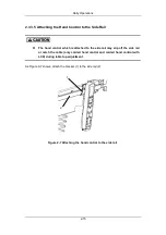
Figure 2-13 Tilt the operating table to right
2.3.4.7 Module Recognition System (optional)
1.
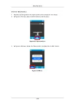
As Figure 2-14 shows, when the leg plate is connected, the icon (A) will be displayed.
2.
As Figure 2-14 shows, when the leg plate is detached, the icon (B) will be displayed.
(
A
)
(
B
)
Figure 2-14 Module recognition
Do not use the individual adjustment function for the leg plates in
conjunction with single-part accessory.
Summary of Contents for HyBase 8300
Page 1: ...Operator s Manual HyBase 8300 HyBase 8500 Operating Table ...
Page 2: ......
Page 84: ...This page is intentionally blank ...
Page 106: ...This page is intentionally blank ...
Page 110: ...This page is intentionally blank ...
Page 122: ...This page is intentionally blank ...
Page 132: ...This page is intentionally blank ...
Page 142: ...This page is intentionally blank ...
Page 150: ...Appendices 10 8 3 Back plate up down up 90 5 down 45 5 ...
Page 158: ...Appendices 10 16 3 Back plate up down up 90 5 down 45 5 ...
Page 175: ...This page is intentionally blank ...
Page 176: ...P N 046 006753 00 2 ...


