1-1
1
System Overview
1.1 Main Components
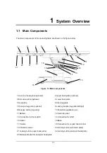
The main components of the operating table are shown in the figure below.
Figure 1-1 Main components
1 Dual-joint head plate (optional)
2 Upper back plate (optional)
3 Extension plate (optional)
4 Lower back plate
5 Seat plate
6 Short leg plate
7 Dual-joint leg plate (optional)
8 Locking handle (leg plate left/right)
9 Release button (leg plate)
10 Potential equalization pin
11 Bellows
12 Override panel
13 Connection for foot switch
14 Connection for USB
15 Castor
16 Base
17 Column
18 Connection for corded hand control
19 Infrared receiver
20 Locking button (extension plate)
21 Locking button (upper back plate)
22 Locking button (dual-joint head plate)
23 Release bracket for dual-joint head plate
1
2
3
4
5
6
7
8
9
13
14
15
17
18
20
10
11
12
16
22
21
23
19
19
Summary of Contents for HyBase 8300
Page 1: ...Operator s Manual HyBase 8300 HyBase 8500 Operating Table ...
Page 2: ......
Page 84: ...This page is intentionally blank ...
Page 106: ...This page is intentionally blank ...
Page 110: ...This page is intentionally blank ...
Page 122: ...This page is intentionally blank ...
Page 132: ...This page is intentionally blank ...
Page 142: ...This page is intentionally blank ...
Page 150: ...Appendices 10 8 3 Back plate up down up 90 5 down 45 5 ...
Page 158: ...Appendices 10 16 3 Back plate up down up 90 5 down 45 5 ...
Page 175: ...This page is intentionally blank ...
Page 176: ...P N 046 006753 00 2 ...


