© 2014 MIMAKI ENGINEERING CO.,LTD.
4.2.2
P.2
4.2.2 STAGGER ADJUST
1
2
3
4
5
6
7
8
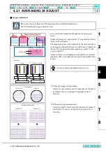
2. Select [#ADJUST] - [STAGGER ADJUST] to execute
adjustment pattern drawing.
3. Carry out the stagger adjustment through the following
procedures.
There is a gap at the right end of pattern on the joint of each
head. Adjust it using this gap.
Check the stagger of each column.
Check that the distance between the Head 1 and 2 is about
140µm.
FUNCTION
#ADJUST
[ENT]
#ADJUST
HEAD ADJUST
[ENT]
#HEAD ADJUST
STAGGER ADJUST [ENT]
#STAGGER ADJUST
PRINT START
[ENT]
Adjustment pattern
drawing
Stagger confirmation point
Head 1
Head 2
<Scope Image>
Rotate the adjustment
lever counter-clockwise.
The position of Head 2
moves backward.
Rotate the adjusting
screw clockwise. The
position of Head 2 moves
forward.
約
140
m
Head 1
Head 2
Head 1
Head 2
Head 1
Head 2
Patterns of effective overlapping and not effective
are printed alternately (They are dotted line-form
part on the middle of the pattern).
R.1.0
MAINTENANCE MANUAL > Adjustment Items > Adjustment Function > STAGGER ADJUST
Model
JV300-130/160
Issued 2014.05.30 Revised
F/W ver.
1.00
Remark
1.0
Rev.
Summary of Contents for JV300-130 A
Page 243: ......
Page 244: ...D500946 10 30052014 MIMAKI ENGINEERING CO LTD 2014 KF FW 1 1 ...


