© 2014 MIMAKI ENGINEERING CO.,LTD.
4.2.6
P.1
1
2
3
4
5
6
7
8
R.1.0
4.2.6 CAPPING
Outline
Adjusts the location for capping. Adjusted value is saved in the system parameter.
Basically, it is not necessary to make adjustment even when cap (and the like) has been replaced.
Adjustment procedure
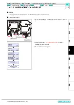
1. Select [#ADJUST] - [CAPPING].
2. Make adjustment so that the cap slider is located at 3 mm to the
right from the uppermost point it has reached on the cap base.
[
] / [
]: Horizontally shifts the cap.
[ENTER]: Finalizes (To Next)
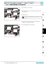
3. Make adjustment so that the clearance between the head and
uppermost point of the cap is set at 0.5 mm.
[
] / [
]: Shifts the cap.
[ENTER]: Finalizes (To Next)
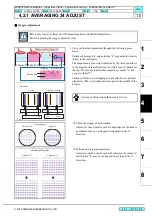
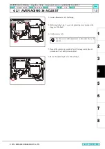
4. Make adjustment so that the clearance between the head and
uppermost point of the cap is set at 1 mm.
[
] / [
]: Shifts the cap.
[ENTER]: Finalizes (To Next)
FUNCTION
#ADJUST
[ENT]
#ADJUST
CAPPING
[ENT]
#CAPPING
CAPPING POS=
2.0
3 mm
#CAPPING
AirPullPOS.=
2.0
0.
5
m
m
#CAPPING
FlushingPOS=
2.0
1m
m
MAINTENANCE MANUAL > Adjustment Items > Adjustment Function > CAPPING
Model
JV300-130/160
Issued 2014.05.30 Revised
F/W ver.
1.00
Remark
1.0
Rev.
Summary of Contents for JV300-130 A
Page 243: ......
Page 244: ...D500946 10 30052014 MIMAKI ENGINEERING CO LTD 2014 KF FW 1 1 ...


