© 2014 MIMAKI ENGINEERING CO.,LTD.
4.2.1
P.4
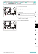
4.2.1 AVERAGING 34 ADJUST
1
2
3
4
5
6
7
8
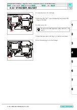
Stagger Adjustment
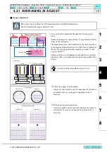
1. Carry out the slant adjustment through the following proce-
dures.
Patterns of columns "a" and columns "b" are printed alternately
(Refer to the left figure).
The magenta and cyan strips (indicated by the thick red arrows
in the diagram on the left) printed over the respective patterns at
the top. These strips indicate that magenta is column "a" and
cyan is column "b".
Patterns of effective overlapping and not effective are printed
alternately (They are dotted line-form part on the middle of the
pattern).
Check the stagger of each column.
Adjust it so that 8 nozzles each for both edges of the head to
be adjusted may be overlapped in alignment in the X
direction.
P
e
r
f
o
r
m
a
n
a
v
e
r
a
g
i
n
g
a
d
j
u
s
t
m
e
n
t
.
Perform an averaging adjustment.
Adjust it so that 8 nozzles each for both edges of column “a”
and column “b” may be overlapped on average in the X
direction.
It is necessary to perform SLANT adjustment before STAGGER adjustment.
After adjusting the stagger, adjust the slant.
Columns “b”
M
C
C
M
Columns “a” Columns “b”Columns “a”
Stagger confirmation point
M
C
C
M
Col. “a”
Col. “b”
Used nozzle
4-color
6-color+W, 8-color
M
C
Lc
Lm
Width x dots
Effective
Not effective
Overlap of dots between the heads is 16 dots.
<Scope Image>
Effective
Not effective
<Adjustment Example>
Columns “b”
Columns “a”
R.1.0
MAINTENANCE MANUAL > Adjustment Items > Adjustment Function > AVERAGING 34 ADJUST
Model
JV300-130/160
Issued 2014.05.30 Revised
F/W ver.
1.00
Remark
1.0
Rev.
Summary of Contents for JV300-130 A
Page 243: ......
Page 244: ...D500946 10 30052014 MIMAKI ENGINEERING CO LTD 2014 KF FW 1 1 ...


