background image


Installer Manual 

Microvideo srl  

www.microvideo.eu 


21 

Chapter 2 –Modules Description 

Radio Remote Control (mod. SY915) 

The figure below shows a reproduction of the SY-915 Radio Remote Controls. Through the 
Remote Control you can interact with the system and receive information on the status of 
the loan with the LED. The Remote Control consists of 5 main parts: 


A. Led Reporting 

B. Red Button 

C. Green Button 

D. Blue Button 1 

E. Blue Button 2 

Interacting with Keys 

Each key of remote control can be associated with 3 categories of actions: 

Entries 

Closings 

Actions 

To implement an action associated with a button you need to press the desired button and 
wait until the LED flashes once RED light, this signal indicates that the remote control has 
forwarded the request to perform the action to the Control Panel. 


Once you press the button you have to wait for an answer from the Central always by the 
flashing LED, the possible responses are: 

Event 

Blink Sequence  

Example 

Action Successfully 
Performed  

1 Blue 


Action Executing failed 

2 Blue 


Arming System Completed 
Successfully 

3 Red 


Arming System Failed, 
Zones in Alarm 

1 Green 

1 Red - 1 Green - 1 Blue (3 times) 


Disarming the Alarm System 
Executed Successfully 

1 Green 


N.B. 

Each time you press a key (and the command is accepted by remote control through a 
flashing red), you should always wait for the response from the plant, indicated by the 
sequence of LEDs in the table above: if the answer is not displayed by the LED means 

Summary of Contents for Synergy SY800

Page 1: ...1 ...

Page 2: ...CLAIMER Every care has been taken in the creation implementation verification of this literature however neither the author nor Microvideo Srl can accept any responsibility for the accu racy of the information described nor provide any guarantee on the performance or results obtained The same applies to any person or company involved in the creation production and distribution of this documentatio...

Page 3: ...vision Function 19 Motion Sensor Module mod SY925 20 Radio Remote Control mod SY915 21 Procedure for Inserting Through Key 22 CHAPTER 3 Installing 23 Installing Control Panel 23 Connection of Voice Module Mod SY 900 23 Connecting siren to an output 24 Sample connection of open collector outputs 24 Connecting Sensor Alarm to Zones 25 Modules Installing on CAN BUS 28 Keyboard Module SY920 Installati...

Page 4: ...48 User Code 49 Installer Codes 49 Macro 49 Actions 50 Events 50 Address Book 52 Vocal Messages 52 GSM Transmission 52 LAN 53 Holidays 53 Alarm Management 54 System Management 54 CHAPTER 5 Plant Management by GSM GPRS Module 55 Incoming Calls and SMS 55 Voice Menu 55 SMS commands 56 APPENDIX B Phisic Terminals SY800 SY810 59 Zones Inputs 59 APPENDIX B Phisic Terminals ST SMOKE 61 Zones Inputs 61 O...

Page 5: ...e goods or otherwise arising from the improper incorrect or otherwise faulty installation or use of these products The warranty covers only defects that result from the proper use of the product It does not cover Misuse or negligence Damage caused by fire flood wind or lightning Vandalism Wear Microvideo srl takes responsibility at its option for repairing or replacing any defective product Improp...

Page 6: ...equirements Installer Manual This installer manual contains informations needed for proper installation programming of a SYNERGY plant It s important to read carefully the manual to understand all the concepts necessary for the proper installation and to familiarize yourself with the functions of the System Usually this manual is provided only in electronic form pdf format User Manual The user man...

Page 7: ...of battery Yes Firmware upgrading of the central Yes Firmware upgrading modules by central Yes USB port Programming Yes Removable Connectors Yes GSM Aboard Yes optional Module Expansion Board Yes Keyboards 4 8 Expansions 7 Proximity Readers 4 8 GSM GPRS 1 Dual Frequency Radio Receivers 2 4 Dual Frequency Radio Modules 10 64 Radio Areas 10 64 Installer Codes 2 User Code 16 64 Proximity Keys 8 64 Ke...

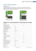
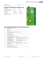
Page 8: ...y 3 RL3 0 5A 24VDC G Fast fuse 2A of protection H Relay 2 RL2 3A 24VDC I Relay 1 RL1 3A 24VDC J USB connector Programming Update FW Monitor K Link LED USB cable connection ON cable plugged Off Power cord not plugged in Link LED USB cable connection ON cable plugged Off Power cord not plugged in L Link LED PC Connection On correct connection Off driver not recognized on PC Link LED PC Connection On...

Page 9: ...and Ground Connectors BUS1 V H L GND CAN Bus Connectors Keyboard Mod SY820 SY820 A Microphone capsule Listening ambient B Input Connector A1 C Connector CAN Bus D speaker E USB connector Programming Log Monitor Zone F Exclusion Tamper Snatch Closed EXCLUDED tamper Open tamper ENABLED Exclusion Tamper Snatch Closed EXCLUDED tamper Open tamper ENABLED G Snatch connector H Led Link USB On USB cable i...

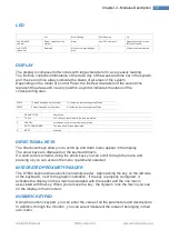
Page 10: ...enting areas Status AREA STATUS Description T TOTAL All The Zones associated to the area are armed P PARTIAL At least one zone in the area was not armed NOT CONFIGURED The zone has NO area associated R REST All areas DIRECTIONAL KEYS The directional keys allow you to scroll up and down menu appear in the display The arrow keys are displayed on the keyboard macro If a valid code is entered using th...

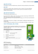
Page 11: ...ject to various types of confirmation depending on the programming You can configure the execution of a macro as immediate confirmation ok button code GSM GPRS Module Mod SY860 The module has two separate connectors to the bus allowing the installation inside the box in the Control Panel or anywhere in the plant by the CAN bus SY860 A Door SIM holder B Tearproof tamper C tamper D Tamper Exclusion ...

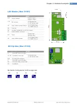
Page 12: ... the system can handle The model SY840 has 8 inputs 1 relay and 3 open collectors Equipped with tamper protection that can be turned off as needed by easy tamper All inputs of the expansion can be configured as NO NO Balanced NC NC WB NC Double Bil Triple Bil Blinds InsImpImp InsImpLiv All outputs FIXED Output SIREN Output PULSE Output Rif SY840 A Tearproof Tamper B F2 Fuse rapid 2A to protect the...

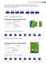
Page 13: ... Off Inserted Jumper On NOT Inserted Jumper DL4 Status Led Flashing Correct function Off Fault Configuration of dip switch for ID assignment Wall Inserter Module Mod SY826 SY825 LS1 Signal Buzzer SW2 Tamper Pressed Rest Released Alarm Bus System Connector Can Bus J2 J3 End line Jumper Off Inserted Jumper On NOT Inserted Jumper DL1 Status Led Flashing Correct function Off Fault SW1 Dip Switch for I...

Page 14: ... use DL2 Led di stato Lampeggiante corretto funzionamento F2 Fusibile Protezione uso futuro SW1 Tamper Pressed Rest Released Alarm JP2 Jumper By Passing tamper Off DISABLED Tamper On ENABLED Tamper BUS Splitter Mod SY930 SY930 J8 System BUS Connector Can Bus JP1 JP2 CAN Bus End line Jumpers Off Inserted Jumper On NOT Inserted Jumper SW2 Dip switch for ID configuration J7 System BUS Connector Can B...

Page 15: ...ncluding the relay and buzzer ADDRESS Dip switch for ID configuration TEST Puts the card in test mode mode in which the alarms do not generate alarms on the alarm relay or buzzer TACIT Temporary Silencing of the buzzer canceled by closing and reopening the door tamper J11 Jumper excluding Buzzer Close Excluded Buzzer Open Active Buzzer PZ1 Buzzer reporting alarms J20 Power supply jack for central ...

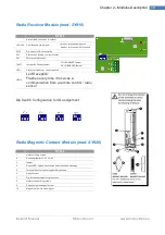
Page 16: ...BLED Tamper On DISABLED Tamper LED1 Status Led flashing correct function LED2 Led Reception Flashes every time it receives a communication from a remote control radio sensor Dip Switch Configuration for ID assignment Radio Magnetic Contact Module mod SY920 SY920 1 Holes for fixing screws 2 Connector Battery 3 6 V 2 4 Ah 3 tamper 4 Report LED lights whenever the module sends a message 5 Terminal bl...

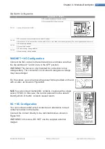
Page 17: ...NC Configuration Connect the NC contact to the terminal block and make sure that the dip switches 1 and 2 are in the OFF position WARNING The device is only intended for connection to low voltage safety The connection to circuits with dangerous voltage may cause danger For the cables you can remove the preset forms provided on the lid with a cutter as shown in Figure M8 N B You can connect multipl...

Page 18: ... position the sensor transmits a signal every four hours of attendance at Control Panel Report Open Close Magnet NC If enabled by DIP switch No 4 the sensor transmits to the Control Panel each change of state of the Magnet example from the closed window to the open window and conversely Similarly for the wired NC contact connected to the clamps of course with the dip switch No 2 in the OFF positio...

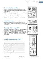
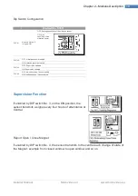
Page 19: ...isabled ON Vibration sensor activated DIP n 3 OFF Supervision disabled ON Supervision enabled DIP n 4 OFF Indication open close disabled ON Indication open close enabled Supervision Function If enabled by DIP switch No 3 on the ON position the sensor transmits a signal every four hours of attendance at Central Report Open Close Magnet If enabled by DIP switch No 4 the sensor transmits to the centr...

Page 20: ... fixed to plastic background 10 3 6 V 2 4 Ah battery connector 11 Tamper with spring 12 Antennas 13 Pyroelectric Sensor 14 PCB Fixing Screws 15 Reset Button 16 Dip Switches 17 Report Led 18 Sensitivity adjustment trimmer 19 Spring Seat tamper button 20 Plastic Cover Hooks Dip Switch Configuration Dip Switch SY921 DIP n 1 OFF LED Warning Light off ON LED Warning Light on DIP n 2 OFF Inhibition time...

Page 21: ...sired button and wait until the LED flashes once RED light this signal indicates that the remote control has forwarded the request to perform the action to the Control Panel Once you press the button you have to wait for an answer from the Central always by the flashing LED the possible responses are Event Blink Sequence Example Action Successfully Performed 1 Blue Action Executing failed 2 Blue A...

Page 22: ...th an inserting there are two possible responses from the LEDs 3 Flashing Red The insertion is was successful after the exit time associated with the areas that are arming the system is armed Multicolor Sequence The insertion of the implant has failed because there are zones in alarm If it is enabled Equipment Forced you can arm the system by pressing the button that is associated with the inserti...

Page 23: ...adapter G Mounting lid holes Secure control unit by anchors at least 6 mm making sure that wiring go through the openings ref D cable glands of the box Connect the power supply in the appropriate terminal block making sure that the fuse of the terminal block is NOT inserted Verify that the tamper placed behind the corner card holder is properly seated Connection of Voice Module Mod SY 900 The Voic...

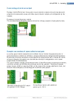
Page 24: ...or presenti sia in centrale che sui moduli di espansione sono in grado di pilotare correnti sino a 50mA e vengono liberamente configurate dall operatore Questo tipo di uscite consente la chiusura se NO o apertura se NC a massa del carico ad esse collegato di seguito sono riportati due esempi di collegamento con o senza supplemento di alimentazione The open collector outputs present both on the Con...

Page 25: ...y by the parent company are of 3 types 10k 3K9 6k8 You can recognize them by the color code from diagrams However the system allows manual configuration of real values of line resistance in three basic states alarm tamper and anti blinding doing so for example you can replace existing plants with its own balancing configurations simply by measuring with a multimeter the resistance of the line in t...

Page 26: ...cuit cutting opening Connecting shutter sensors and balances For the connection of inertial sensors or shutter you can make two different types of connection Normally closed normally closed single balancing Normally closed The classic link normally closed NC to detect only two states of the sensor rest and alarm nothing is in fact reported in the case of cutting wires or short circuit The alarm st...

Page 27: ...u 27 CHAPTER 3 Installing Also valid for connection of shutter sensor Examples of zone connections Connections NC NO Single balance Connections Double balance Connections Triple balance Connections Also valid for balanced connection of shutter sensor ...

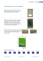
Page 28: ...rtant to connect a 120ohm resistance Keyboard Module SY920 Installation Gently separate the base of the keyboard from front panel Fix the base of the keyboard on the wall ref A taking care to pass bus wiring and possibly sensor wiring in cable hole on the right ref B Connect Bus and sensor wiring in terminal keyboard Thread the bottom of the front panel of the keyboard in the bottom support of the...

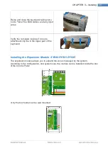
Page 29: ...rify the complete closing of 4 doors attachment clip the in the upper part of the keyboard Installing the Expansion Module SY840 SY841 SY845 The expansion module allows you to expand the zones managed by the system According to the configuration and system size the module can be installed inside the box of the Control Panel or by the box holder can be wall mounted ...

Page 30: ...talling Installing GSM GPRS SY860 SY861 Module The GSM GPRS module can be installed inside the box of the plant through the plate holder and connected to the panel via a secondary Bus or it can be installed anywhere in system as the other modules inside the Box holder ...

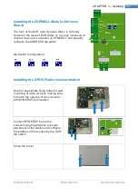
Page 31: ...or it can be installed anywhere in system as the other modules inside the Box holder Check the proper position of tamper lever SW2 In case the LAN module was wired as the last module on the bus close jumpers JP3 and JP4 to enable the end line resistors Connect the LAN cable into the connector NOTE After making changes to LAN parameters by keyboard or software SynergyPro wait at least 45 seconds to...

Page 32: ...ide the opening Connect bus cable to connector J4 paying attention to correct connection Configure the address of ID module using the dip switch SW1 In case the module was wired as the last system module close jumper J2 and J4 to enable line terminations Place the module over the base and provide to insert screws top and bottom taking care at correct seating of the of antiopening tamper spring Dip...

Page 33: ...nnect cables bus to connector j2 paying attention to correct connection Configure the address of ID module using the dip switch SW2 In case the module was wired as the last module system close jumpers J14 and J15 to enable line terminations Dip Switch Configuration Installing the SY930 Bus Isolator Repeater Module The module SY930 can be housed inside an electrical junction box thanks to its very ...

Page 34: ...o connector J2 SYNERGY and properly configure the ADDRESS dip switch Dip Switch Configuration Installing the SY910 Radio receiver module Use the appropriate fixing holes for wall mounting of radio receiver making sure to match the opening of the connector with SYNERGY bus location Connect SYNERGY bus to the connector paying attention to proper placement of the cables and configure the address of t...

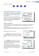
Page 35: ...tween the sensor and the support surface a strip of insulating material plastic wood with a thickness of 2 cm Before connecting sensor battery pleas make connections and schedules on the dip switches see chapter 2 depending on the type of system required Opening and closing of the casing OPENING Open the plastic casing of the sensor by levering with a screwdriver in the invitation present on the c...

Page 36: ... a corner Its range of action should never be covered by obstacles eg closets Do not install the sensor in front of windows to avoid direct exposure to the outside lights sun headlights etc Before connecting sensor battery do the programming on the dip switches see chapter 2 depending on the system required In Fig I7 is described the action of the volumetric device SY925 wall mounted without the j...

Page 37: ...e battery in accordance with regulations If the battery fluid should leak replace it immediately taking care to wipe the housing and thoroughly wash your hands in case of contact with fluid from the battery Configuring Module Address All modules at the moment of purchase are configured with the address 1 After installing system you need to configure the address of the modules that compose it Addre...

Page 38: ...xpansion Module The expansion modules must be configured through dip switches on the PCB Addressing GSM GPRS Module The dip switches present in the GSM GPRS Module must be left in the default state while it is ESSENTIAL to properly configure the GSM bus parameter in the following menu available on the keyboard indicating whether the module is on the Inside bus or on the Outside bus INTERNAL BUS Th...

Page 39: ...possible through the keypads or through SynergyPro software It allows the display of Real Time Zone Status the possible states are Disabled Rest Alarm Sat Fault Tamper Using software SynergyPro you can verify the correct operation by graphic user interface Or you can check the status of modules fuses and tampers For more details please refer to the reading of the User Software SynergyPro Menu Inst...

Page 40: ... configure all parameters of the plant Use the arrows to move between the menus Pressing the OK button you enter the menu while pressing the ESC key you return to the previous menu level The installer menu includes the following menu giving access to the configuration of each parameter system General Parameters Zone Radio Zone Outputs AND zones Expansions Areas Timer Keyboards RFID keys Readers Wa...

Page 41: ...ith a confirmation SMS for recepting command RING GSM module replies with a confirmation phone call for recepting command VocMsgOrd GSM Playing order of 3 warning voice messages when a call is made Voice Menu NO Vocal Menu of Keyboard Disabled Yes Vocal Menu of Keyboard Enabled PasswordSize 4char 4 characters 5char 5 characters 6char 6 characters TimeoutLogout 0 300 Time sec of automatic logout of...

Page 42: ...balance generates an alarm after delay time Firefighting ALWAYS armed Zone every unbalance generates an alarm Antirobbery ALWAYS armed Zone every unbalance generates an alarm No Panic ALWAYS armed Zone every unbalance generates an alarm 24H ALWAYS armed Zone every unbalance generates an alarm Technological ALWAYS armed Zone every unbalance generates an event never alarms Following Zone If the Zone...

Page 43: ...very unbalance generates an alarm 24H ALWAYS armed Zone every unbalance generates an alarm Technological ALWAYS armed Zone every unbalance generates an event never alarms Follow Chase If the Zone that must be chased is at rest the other one behaves as Snapshot Alarm Cycles NoConfig 0 127 Alarm cycles after which the alarms of the Zone will be ignored for that specific insertion however they will c...

Page 44: ... of the two AND wired zones RadioZone1 RadioZone64 Configuration of the Second of the two Radio wired zones Time 0 300 Time seconds within which BOTH the two zones must be unbalanced because an alarm event is generated Direction NO The order in which the Zones are unbalanced is not important to generate an alarm event YES The order in which the Zones are unbalanced is important to generate an alar...

Page 45: ...u can t apply a delay see 4 2 1 Warning Time 1 30 Warning time min displayed on keyboards in order to inform the user about timer enabling During this time the user can delay the Timer Monday 24 00 Start of Monday time band end of Monday time band To switch selection between fields Start Time band and End Time band use the special FN key and the arrow keys to change value of selected field Tuesday...

Page 46: ...ition menu 2 Move the key to the keyboard until the second line of the display shows the serial number associated with the key 3 Press OK button to finish the procedure Readers Parameter Options Description Enable YES Reader enabled NO Reader disabled Description 12 Characters Reader Description Description appears during configuration either by keyboard then by SynergyPro SW in every log and in S...

Page 47: ...ime in seconds of delay of fog machine Shot on Alarm Enable Fog Hold Function Yes Fog Holding Function Enabled NO Fog Holding Function Disabled Fog Hold Rest 5 15 Pause time in minutes holding fog cycle before next shot Fog hold Shot time 1 2 Shot The Shot during fog hold cycle will take half of Alarm Shot time 1 4 Shot The Shot during fog hold cycle will take a quarter of Alarm Shot time Fog Hold...

Page 48: ...eyMacro NoConfig Macro1 Macro36 Setting of the macro to be associated with red key of Remote Control GreenKeyMacro NoConfig Macro1 Macro36 Setting of the macro to be associated with verde key of Remote Control BlueKey1Macro NoConfig Macro1 Macro36 Setting of the macro to be associated with blue1 key of Remote Control BlueKey2Macro NoConfig Macro1 Macro36 Setting of the macro to be associated with ...

Page 49: ...K Key After pressing the macro key you need to press the OK button Insert Code After pressing the macro key you need to insert a valid code Macro 1 8 NoConfig Macro1 Macro36 Configuring the user macro to associate with the key F1 F4 e FN 1 FN 4 of the keyboard Installer Codes Parameter Options Description Code Insert Edit of the password of installer code Macro Parameter Options Description Descri...

Page 50: ...ges triggered when something happens in the system Each event can be associated with an initial macro namely a macro that is executed when the event occurs and a final macro that runs when you restore the conditions before the event For example if we consider the event No 220 network the initial macro is executed when there is a lack of power supply while the final macro reset is performed when th...

Page 51: ...SM Damage The control unit performs continuous monitoring of mobile network and GSM module and in the event of network failure or fault of the module it runs the associated MACRO Fuses Damage The control unit performs continuously checks of various fuses mounted on The unit and on Expansions Firefighting Activating a zone programmed as Firefighting Panic Activating a zone programmed as Panic Param...

Page 52: ...sabled Description 12 characters Phone Number Description Description appears during configuration either by keyboard then by SynergyPro SW in every log and in SMS messages relative to phone number Number 18 digits Phone number Configuration Ring Macro NoConfig Macro1 Macro36 Configuring macro to run when the phone number rings to GSM module Vocal Messages Parameter Options Description Listen Msg1...

Page 53: ...ess of LAN Module Netmask xxx xxx xxx xxx Netmask of LAN Module Gateway xxx xxx xxx xxx Gateway of LAN Module DNS xxx xxx xxx xxx DNS of LAN Module IP ServerAPP xxx xxx xxx xxx APP Server IP address necessary to LAN module for the proper functioning of phone APPs ServerAPP Gate 0 65000 APP Server Gate for transmission NB let default value at 6500 VIGILANCE Parameter Options Description Customer Co...

Page 54: ...elds day month year using the special FN key and arrow keys to edit the value of the selected field TimeCfg 00 00 23 59 Allows you to change the current time to switch the selection between fields hour and minute using the special FN key and arrow keys to edit the value of the selected field DayCfg Monday Sunday Allows you to change the current day of week Buzz Volume 1 4 Setting up the Audio Volu...

Page 55: ...fonata preme un qualsiasi tasto del Tastierino Numerico del proprio cellulare Moreover if the User before the end of the voice call press the 9 the system deletes all Call Queue ie all calls and SMS messages are deleted copda Each message Vocal consists of 3 parts 1 Message Descriptive Plant 2 Message Descriptive Event occurred 3 Message Descriptive element that triggered the event The sequence in...

Page 56: ...em is set up correctly is possible to make run a macro to the system using a simple ring made from the phone to the SIM number of the GSM module SMS commands You can interact with the dialer via SMS The basic composition of the message is code command parameter Available Command assuming that the user code is 111111 Plant Status 111111 status Restores actual state of every Area Residual Credit 111...

Page 57: ...er interacts with a keyboard by making a Login or consulting Log of Alarm Memory Led Alarm Diagnostics stops flashing CONTROL UNIT SY800 SY810 Main Module System processes all data provided by modules that make up the system is responsible for storing all the transactions carried out and trigger the actions configured a result of Events RFID KEY Portable univocal apparatus associated with a user t...

Page 58: ...ole system or start macro view state data of the Plant every keyboard also has an integrated RFID key reader for the recognition of keys previously configured REMOTE ASSISTANCE Procedure started by User by SY820 keyboardor SY860 combiner that triggers Internet connection of GSM SY860 Module SY860 communicates its IP address by SMS or by SY820 keyboard display that must be communicated to the insta...

Page 59: ...ansion 1 Input A7 Zone 56 Expansion 6 Input A7 Zone 17 Expansion 1 Input A8 Zone 57 Expansion 6 Input A8 Zone 18 Expansion 2 Input A1 Zone 58 Expansion 7 Input A1 Zone 19 Expansion 2 Input A2 Zone 59 Expansion 7 Input A2 Zone 20 Expansion 2 Input A3 Zone 60 Expansion 7 Input A3 Zone 21 Expansion 2 Input A4 Zone 61 Expansion 7 Input A4 Zone 22 Expansion 2 Input A5 Zone 62 Expansion 7 Input A5 Zone ...

Page 60: ...Installer Manual Microvideo srl www microvideo eu 60 ...

Page 61: ...ut A4 Zone 18 Expansion 2 Input A1 Zone 58 Fog Machine 3 Input A5 Zone 19 Expansion 2 Input A2 Zone 59 Fog Machine 3 Input A6 Zone 20 Expansion 2 Input A3 Zone 60 Fog Machine 4 Input A1 Zone 21 Expansion 2 Input A4 Zone 61 Fog Machine 4 Input A2 Zone 22 Expansion 2 Input A5 Zone 62 Fog Machine 4 Input A3 Zone 23 Expansion 2 Input A6 Zone 63 Fog Machine 4 Input A4 Zone 24 Expansion 2 Input A7 Zone ...

Page 62: ... 2 OC3 Output 13 Expansion 2 Relè Output 14 Expansion 3 OC1 Output 15 Expansion 3 OC2 Output 16 Expansion 3 OC3 Output 17 Expansion 3 Relè Output 18 Expansion 4 OC1 Output 19 Expansion 4 OC2 Output 20 Expansion 4 OC3 Output 21 Expansion 4 Relè Output 22 Expansion 5 OC1 Output 23 Expansion 5 OC2 Output 24 Expansion 5 OC3 Output 25 Expansion 5 Relè Output 26 Expansion 6 OC1 Output 27 Expansion 6 OC2...

Page 63: ...r jumper J12 3 When you reboot the Control Unit with the Jumper J13 inserted the LED DL1 and DL2 are off 4 After about 5 sec turns on the LED DL1 indicating that Installer codes and the Code 1 have been reset N B If you want to end here the steps you need to take off within 5 seconds the reset jumper J13 5 After about 10 seconds LED DL2 turns on this indicates that the DB was reset everything back...

Page 64: ...18 31 Zone 19 32 Zone 20 33 Zone 21 34 Zone 22 35 Zone 23 36 Zone 24 37 Zone 25 38 Zone 26 39 Zone 27 40 Zone 28 41 Zone 29 42 Zone 30 43 Zone 31 44 Zone 32 45 Zone 33 46 Zone 34 47 Zone 35 48 Zone 36 49 Zone 37 50 Zone 38 51 Zone 39 52 Zone 40 53 Zone 41 54 Zone 42 55 Zone 43 56 Zone 44 57 Zone 45 58 Zone 46 59 Zone 47 60 Zone 48 61 Zone 49 62 Zone 50 63 Zone 51 64 Zone 52 65 Zone 53 66 Zone 54 6...

Page 65: ...acro 18 134 Macro 19 135 Macro 20 136 Macro 21 137 Macro 22 138 Macro 23 139 Macro 24 140 Macro 25 141 Macro 26 142 Macro 27 143 Macro 28 144 Macro 29 145 Macro 30 146 Macro 31 147 Macro 32 148 Macro 33 149 Macro 34 150 Macro 35 151 Macro 36 152 Key 1 153 Key 2 154 Key 3 155 Key 4 156 Key 5 157 Key 6 158 Key 7 159 Key 8 160 Key 9 161 Key 10 162 Key 11 163 Key 12 164 Key 13 165 Key 14 166 Key 15 16...

Page 66: ...arm 228 Fuse failure 229 disarm Failure 230 Not Sufficient pass 231 Areas already Insert 232 Forced Arming 233 Inserting Failure 234 Press any key to confirm the call 235 Disconnect area 236 Remote assistance request 237 Wrong code 238 Fixed installer code 239 Correct Master Code 240 Correct User Code 241 Code Out of Hour 242 Disabled code 243 Code Inst System not Disarmed 244 Press 245 For 246 Ma...

Page 67: ...5 341 Radio Module 6 342 Radio Module 7 343 Radio Module 8 344 Radio Module 9 345 Radio Module 10 346 Radio Module 11 347 Radio Module 12 348 Radio Module 13 349 Radio Module 14 350 Radio Module 15 351 Radio Module 16 352 Radio Module 17 353 Radio Module 18 354 Radio Module 19 355 Radio Module 20 356 Radio Module 21 357 Radio Module 22 358 Radio Module 23 359 Radio Module 24 360 Radio Module 25 36...

Page 68: ... Radio Module 44 Radio Module 45 Radio Module 46 Radio Module 47 Radio Module 48 Radio Module 49 Radio Module 50 Radio Module 51 Radio Module 52 Radio Module 53 Radio Module 54 Radio Module 55 Radio Module 56 Radio Module 57 Radio Module 58 Radio Module 59 Radio Module 60 Radio Module 61 Radio Module 62 Radio Module 63 Radio Module 64 Radio Remote Control 1 Radio Remote Control 2 Radio Remote Cont...

Page 69: ...CHAPTER 4 Programming Control Unit Installer Manual 69 Radio Remote Control 31 Radio Remote Control 32 ...

Reviews: