Installer Manual
Microvideo srl
www.microvideo.eu
15
Chapter 2 –Modules Description
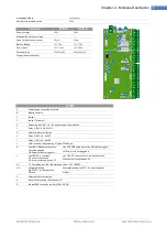
DVR WALL 4N-8N
WALL 4N-8N
J7
Bus connectionIRBox
J3
Channels 1 and 2 for camera supply
J4
Channels 3 and 4 for camera supply
J2
SYNERGY BUS connector
DL3
Fuse status line 1
DL4
Fuse status line 2
DL5
Fuse status line 3
DL6
Fuse status line 4
FUNCTION
Function Switch
SW-1: Future use
SW-2:
ON
→
Disable recording and general
alarm, excluding the relay and the Buzzer
OFF
→
Enable recording and general
alarm, including the relay and buzzer
ADDRESS
Dip-switch for ID configuration
TEST
Puts the card in "test mode" mode in which the alarms do not generate
alarms on the alarm relay or buzzer
TACIT
Temporary Silencing of the buzzer, canceled by closing and reopening
the door tamper
J11
Jumper excluding Buzzer
Close = Excluded Buzzer
Open = Active Buzzer
PZ1
Buzzer reporting alarms
J20
Power supply jack for central unit synergy
DL1
Presence of electrical network
AC1
Power Connector
AC2
Power Connector
ON
Jumper supplying DVR and
Cameras
Closed = DVR and Cameras
powered
Open = DVR and Cameras not
powered
DL2
Status Led flashing = correct function
Dip Switch Configuration for ID assignment
ID1 ID2 ID3 ID4
Summary of Contents for Synergy SY800
Page 1: ...1 ...
Page 60: ...Installer Manual Microvideo srl www microvideo eu 60 ...


