Installer Manual
Microvideo srl
www.microvideo.eu
13
Chapter 2 –Modules Description
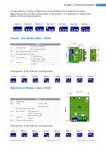
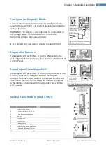
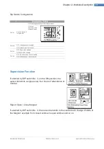
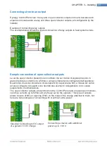
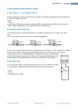
It’s important to correctly configure the switch identifying the expansion module.
Depending on the number of expansions in the system, it is essential to configure the
switch as in the following figures
Inserter Jack Module (Mod. SY825)
SY825
J6
Tearproof Tamper
Chiuso: tamper ESCLUSO
Aperto: tamper ABILITATO
SW2
Dip-Switch per la configurazione dell'ID
J2
Bus System Connector (Can Bus)
J14-J15
End line Jumper
Off: Inserted Jumper
On: NOT Inserted Jumper
DL4
Status Led
Flashing: Correct function
Off: Fault
Configuration of dip switch for ID assignment
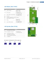
Wall Inserter Module (Mod. SY826)
SY825
LS1
Signal Buzzer
SW2
Tamper
Pressed = Rest
Released = Alarm
Bus System Connector (Can Bus)
J2-J3
End line Jumper
Off: Inserted Jumper
On: NOT Inserted Jumper
DL1
Status Led
Flashing: Correct function
Off: Fault
SW1
Dip Switch for ID Configuration
Configuration of dip switch for ID assignment
Expansion 1
Expansion 2 Expansion 3
Expansion 4
Expansion 5 Expansion 6 Expansion 7
Reader 1 Reader 2
Reader 3
Reader 4 Reader 5 Reader 6 Reader 7 Reader 8
Reader 1 Reader 2
Reader 3
Reader 4 Reader 5 Reader 6 Reader 7 Reader 8
Summary of Contents for Synergy SY800
Page 1: ...1 ...
Page 60: ...Installer Manual Microvideo srl www microvideo eu 60 ...


