Installer Manual
Microvideo srl
www.microvideo.eu
18
Chapter 2 –Modules Description
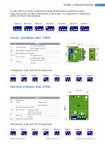
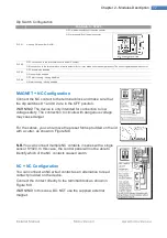
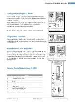
Configuration Blinds
Connect the sensor to terminal block shutter and make
sure that dip switch # 2 is in the ON position to enable the
counter function.
WARNING! The device is only intended for connection to
low voltage safety. The connection to circuits with
dangerous voltage may cause danger.
N.B. Connect only one sensor shutter module SY920.
Diagnostics Function
If enabled by DIP switch No. 3, on the ON position, the
sensor transmits a signal every four hours of attendance at
Control Panel.
Report Open/Close Magnet/NC
If enabled by DIP switch No. 4, the sensor transmits to the
Control Panel each change of state of the Magnet:
example from the closed window to the open window and
conversely. Similarly for the wired NC contact connected
to the clamps, of course with the dip switch No. 2 in the
OFF position.
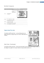
Inertial Radio Module (mod. SY921)
SY921
1
Holes for fixing screws
2
Connector Battery 3.6 V 2.4 Ah
3
Setup functions Dip-Switches
4
Tamper
5
Reporting Led
6
Reed Contact
7
Vibration Sensor
8
Holes for fixing screws of the base
9
Pegs closing the magnet holder
10
Magnet Holder Lid with magnet
Summary of Contents for Synergy SY800
Page 1: ...1 ...
Page 60: ...Installer Manual Microvideo srl www microvideo eu 60 ...


