background image

S

AMPLE

T

UBE

I

NSTALLATION

The equipment images in this topic may differ slightly from your equipment; however,
the instructions are the same unless otherwise noted.

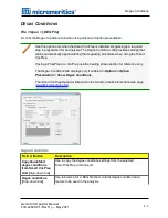
1. Remove the sample tube stopper, if used.
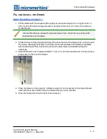
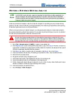
2. Place the connector nut, ferrule, and O-ring onto the sample tube stem. The sample tube fer-

rule is tapered slightly on one end, however it may be installed with the tapered end in the
up or down position.

A. Sample tube or balance tube
B. Connector nut

C. O-ring
D. Ferrule

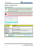
If analyzing samples with a surface area of 1.0 m

2

or less, use filler rods in the sample

and balance tubes. See

Analyze Samples with a Total Surface Area of 1.0m2 or

Less on page A - 1

.

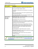
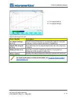
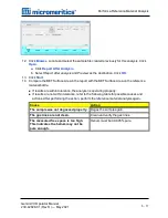
3. Attach the sample tube to the analysis port. Ensure it is fully in the port. Secure it in place by

screwing the connector nut into the analysis port. Hand tighten the connector nut.

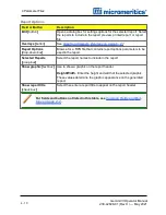
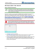
4. If the balance tube is not installed, attach it to the balance port following the above pro-

cedures. If a filler rod was used in the sample tube, one must be used in the balance tube.

It is not necessary to remove and replace the balance tube between analyses unless
it has been contaminated or if using a different size sample tube.

Sample Tube Installation

Gemini VII Operator Manual
239-42828-01 (Rev H ) — May 2021

5 - 9

Summary of Contents for GEMINI VII

Page 1: ...OPERATOR MANUAL 239 42828 01 May 2021 Rev H GEMINI VII SURFACE AREA ANALYZER ...

Page 2: ...rk of Micromeritics Instrument Corporation Microsoft and Windows are registered trademarks of Microsoft Corporation Copyright The software described in this manual is furnished under a license agreement and may be used or copied only in accordance with the terms of the agreement ____________________________________________________________________________ Copyright 2013 2021 Micromeritics Instrumen...

Page 3: ...igations of this warranty will be limited under the following conditions 1 Certain products sold by MICROMERITICS are the products of reputable manufacturers sold under their respective brand names or trade names We therefore make no express or implied warranty as to such products We shall use our best efforts to obtain from the manufacturer in accordance with his customary prac tice the repair or...

Page 4: ...ity testing of catalysts The company has R D and manufacturing sites in the USA UK and Spain and direct sales and service operations throughout the Americas Europe and Asia Micromeritics systems are the instruments of choice in more than 10 000 laboratories of the world s most innovative companies prestigious government and academic institutions Our world class scientists and responsive support te...

Page 5: ...x 1 770 662 3696 www Micromeritics com Instrument Service or Repair Phone 1 770 662 3666 International contact your local distributor or call 1 770 662 3666 Service Helpdesk Micromeritics com Micromeritics Learning Center Phone 1 770 662 3607 www Micro edu Contact Us Gemini VII Operator Manual 239 42828 01 Rev H May 2021 iii ...

Page 6: ...ns instructions for installations in standard and 21CFR11 environments For instructions on installing the software in a 21CFR11 environment see the Confirm Administrator Guide part number 004 42821 01 The following symbols or icons indicate safety precautions and or supplemental information and may appear in this manual NOTE Notes contain important information applicable to the topic CAUTION Cauti...

Page 7: ...weighs approximately 32 kg 75 lb n Always pay attention to the safety instructions provided on each label affixed to the instrument and do not alter or remove the labels When inspecting the instrument ensure that the safety labels have not become worn or damaged n The Gemini VII sound level is below 80 dBA Hearing protection is optional n The Gemini VII has a safety shield Ensure it is in place wh...

Page 8: ...a larger dewar and longer sample tubes for extended analyses This model also is equipped with a P0 tube Most application features are available on all three models with the exception of a continuous P0 measurement and a few reports The instrument is intended to be operated by trained personnel familiar with the proper operation of the equipment recommended by the manufacturer as well as relevant h...

Page 9: ...Supplies x o o o o o Printed Circuit Boards x o o o o o Cables Con nectors Transducers x o o o o o Hazardous Substances Table o Hazardous substance is below the specified limits as described in SJ T11363 2006 x Hazardous substance is above the specified limits as described in SJ T11363 2006 The Environmentally Friendly Use Period EFUP for all enclosed products and their parts are per the symbol sh...

Page 10: ......

Page 11: ...ns for the Gemini VII 1 6 2 About the Software 2 1 Menu Structure 2 1 Common Fields and Buttons 2 2 File Status 2 5 Keyboard Shortcuts 2 7 Option Presentation 2 9 Libraries 2 11 Methods 2 12 Configure the Analyzer 2 14 Unit Selection 2 14 Unit Configuration 2 15 Instrument Status 2 16 Show Instrument Log 2 16 Show Instrument Schematic 2 17 Show Status 2 20 Export Files 2 21 Gemini VII Operator Man...

Page 12: ...ptive Properties 4 2 Analysis Conditions 4 3 Degas Conditions 4 7 Report Options 4 9 5 Perform an Analysis 5 1 Dewar Precautions 5 1 Prepare for Analysis 5 3 Clean and Label Sample Tubes 5 3 Determine the Sample Mass 5 6 Degas the Sample 5 8 Sample Tube Installation 5 9 Fill and Install the Dewar 5 11 Perform a Sample Analysis 5 12 Perform an Empty Tube Analysis 5 14 Perform a Reference Material A...

Page 13: ...t Examples 6 31 BJH Adsorption Report 6 31 Horvath Kawazoe Report 6 32 Isotherm Linear Plot Report 6 33 Sample Log Report 6 34 t Plot Report 6 35 Validation Report 6 36 7 Selected Report Options 7 1 Alpha S Method Report 7 2 BET Surface Area Report 7 4 BJH Adsorption Desorption Report 7 6 DFT Pore Size Report 7 12 DFT Surface Energy Report 7 14 Dollimore Heal Adsorption Desorption Report 7 15 Dubi...

Page 14: ...ransducers 9 3 Zero Pressure 9 4 Sample Servo Valve 9 5 Load Calibration from File 9 6 Save Calibration to File 9 6 10 Troubleshooting 10 1 Parts And Accessories 10 4 Power 10 4 Safe Servicing 10 5 Guidelines for Connecting Gases 10 6 Clean and Verify the Gas Line 10 8 Replace a Gas Cylinder 10 11 Enable Manual Control 10 14 Perform a Leak Test 10 15 Perform Reference Material Analysis 10 17 Perfo...

Page 15: ... a Power Failure 10 26 Oil based Vacuum Pump 10 26 A Analyze Samples with a Total Surface Area of 1 0m2 or Less A 1 B DFT Models B 1 Models Based on Statistical Thermodynamics B 1 Models Based on Classical Theories B 14 DFT Model References B 17 C Exported Data Example C 1 D O ring Compatibility D 1 E Worksheets E 1 Sample Data Worksheet for Gas Adsorption E 2 Gemini VII 2390 EU Declaration of Con...

Page 16: ......

Page 17: ...r Sample safety shield Closes to cover the Dewar Power indicator light Blinks when power is applied to the analyzer illuminates when the analysis program is initiated and ready for operation Balance port and balance tube The balance tube is identical to the sample tube This design negates free space errors introduced by thermal gradient vari ations or by initial mis measurement of free space P0 po...

Page 18: ... Allows placement of the Dewar around the sample and P0 tubes The elevator is raised automatically when the analysis is started and lowers automatically upon completion Front Components continued BACK PANEL COMPONENTS A Power connector B Power switch C RS232 connector for service personnel use D USB ports not used E Ethernet port F Keypad connection used only wit keypad con figurations G Helium in...

Page 19: ...ia n Achieve vacuum levels of 20 μmHg at the analyzer inlet n Contain an anti suckback valve to prevent vacuum pump oil from back streaming into the analyzer in the event of a vacuum pump failure n Contain an NW16 inlet port for connection to the analyzer A device to reduce oil vapor backstreaming is recom mended The vacuum pump must have an anti suckback valve to prevent oil from being admitted i...

Page 20: ... reference Samples can also be prepared started and completed independently There is no need to wait for samples on other ports to finish Front panel buttons allow a QuickStart operation with preprogrammed conditions Up to three additional Smart VacPrep degassers can be connected to one computer permitting 24 preparation ports to be used The Smart VacPrep is the recommended degassing unit VacPrep ...

Page 21: ...ogen is used as the adsorbate gas they should be of the following purity or better n Helium purity of 99 9 For analysis of materials with very low surface areas Micromeritics recommends use of helium with purity of 99 995 CGA 580 n Nitrogen purity of 99 9 For analysis of materials with very low surface areas Micromeritics recommends use of nitrogen with purity of 99 995 CGA 580 CRYOGEN REQUIREMENT...

Page 22: ... wet locations Altitude 2000 m max Pollution degree of the intended environment 2 Degree of Ingress Protection IPX0 Environment Adsorbate Optimized for nitrogen in a liquid nitrogen sample bath Gemini may be used with non corrosive adsorbate gases having vapor pressures at both room and bath temperatures that are acceptably high relative to the resolution of the 1 000 mmHg pressure trans ducer Typ...

Page 23: ...ucer manufacturer specification Better than 0 5 full scale Pressure Measurement Standard Tube n Gemini VII 2390a and 2390p 0 95 cm 3 8 in OD 15 5 cm 6 1 in long with 6 5 cm3 of volume Sample capacity is approx imately 2 0 cm3 n Gemini VII 2390t 0 95 cm 3 8 in OD 20 5 cm 8 1 in long with 8 9 cm3 of volume Sample capacity is approximately 2 0 cm3 Dewar n Gemini VII 2390a and 2390p 8 hours n Gemini V...

Page 24: ... be installed on a network drive with shared access Multiple users cannot operate the application at the same time 10 Base T or 100 Base T Ethernet Port If the computer is to be connected to a network two Ethernet ports are required If more than one Ethernet based unit is connected to the same computer an Ethernet switch will also be required If a Smart VacPrep is to be used an Ethernet switch is ...

Page 25: ...RE All program functions use standard Windows menu functionality The title bar contains a Unit n If multiple analyzers are installed ensure the appropriate unit is selected before continuing Option Description File Use to manage files used by the application such as sample files ana lysis conditions files report options files etc Unit n Use to perform analyses calibrations and other analyzer opera...

Page 26: ...port parameters windows the From To fields are enabled when Autoscale options are not selected Enter the starting and ending val ues for the x and or y axes Bar Code default field label name Use to enter additional information about the sample such as a sample lot number sample ID etc Browse Searches for a file Cancel Discards any changes or cancels the current process Clear Use to clear the table...

Page 27: ...her type files The list will contain file name date time the file was created or last edited file identification and file status Name Contains a list of files in the selected directory or library Next Moves to the next window or next step OK Saves and closes the active window Open Opens the selected file Alternatively double click the file name in the Name column to open the file Prev Moves to the...

Page 28: ...d alone file such as Analysis Conditions or Report Options Start Starts the report test analysis or operation Start Date Displays a calendar to select the start date for the report View Operation Displays the data from the current analysis Instrument Log Displays recent analyses calibrations errors or messages Instrument Schematic Displays a schematic of the analyzer system Common Fields and Butto...

Page 29: ... files that have been used in an automatic degas operation but have not been analyzed This status is applicable only if using the Smart VacPrep degasser Preparing Sample files that are currently being used in an automatic degas operation This status is applicable only if using the Smart VacPrep degasser File Status File Type File Name Extension Alpha s Curve1 ALS Adsorptive Properties ADP Analysis...

Page 30: ...kup language XML File Types for Printing or Exporting 1 Saves the relative pressures and corresponding thicknesses as an ASCII text file These data are derived by dividing the condensed volume of adsorptive by the selected surface area The density conversion factor in the adsorptive properties file is used to convert quantity adsorbed to volume of condensed adsorptive 2 6 Gemini VII Operator Manua...

Page 31: ...F Opens the File menu Alt F4 Exits the program If files are open with unsaved changes a prompt to save changes displays Alt H Opens the Help menu Alt I Opens the Options menu Alt R Opens the Reports menu Alt V Opens the Smart VacPrep menu Alt W Opens the Window menu Ctrl N Opens a new sample file Ctrl O Opens the File Selector window Ctrl P Opens the File Selector to start a report from a selected...

Page 32: ...ses all open reports F10 Opens the Heat of Adsorption window Shift F2 Opens the File Selector window listing sample information files Shift F9 Opens the shortcut menu of either the selected component on the analyzer schematic when manual control is enabled or onscreen reports Keyboard Shortcuts continued 2 8 Gemini VII Operator Manual 239 42828 01 Rev H May 2021 ...

Page 33: ...ted That same password must be entered to change to the Basic or Advanced display option This display type is typically used in laboratories such as the pharmaceutical industry where analysis conditions must remain constant The Advanced option is not available in the view selector at the bottom of the window when using the Restricted display option Always Open Edit View Opens files with a Complete...

Page 34: ...is required if using Restricted format Option Presentation Examples Advanced view Basic or Restricted view A sample file must be created for each analysis The file can be created prior to or at the time of analysis The sample file identifies the sample guides the analysis and specifies report options 2 10 Gemini VII Operator Manual 239 42828 01 Rev H May 2021 ...

Page 35: ...ve providing access to all files Even though libraries do not store actual sample and parameter files folders can be added or removed within each library One library can include up to 50 folders Other items such as saved searches and search connectors cannot be included When removing a folder from a library the folder and its contents are not deleted from the original file storage location However...

Page 36: ...ion A Method determines the default sample identification format and sequence number A Method is a template of specifications that go into a newly created sample file It allows for the definition of complete sets of parameters for each type of sample commonly analyzed so that only a single selection is required for each new sample file created The Method drop down list displays only those methods ...

Page 37: ... number included as part of the identification Sample Operator Submitter Bar Code text box These field labels may be renamed and the new label becomes a part of all new sample files Sequence Number text box Specify a default numeric string to be used as a prefix in the Sample field when a new sample file is created This number increments with each sample file created Default Methods Methods Gemini...

Page 38: ...ptions Units Use to specify how data should appear on the application windows and reports This menu option is not available if using Restricted option presentation in a standard installation environment 2 14 Gemini VII Operator Manual 239 42828 01 Rev H May 2021 ...

Page 39: ...is The value in this field is used in calculating free space Change IP button Click to display the Unit IP Setup window Use to change the IP address and subnet mask assigned during installation Do not edit these fields unless instructed by a Micromeritics Service Rep resentative Delete Data From Instrument button Restores the controller to factory defaults For fields and buttons not listed in this...

Page 40: ...cription Add Log Entry button Use to enter information to appear in the sample log report that can not be recorded automatically through the application Click the but ton again to enter multiple log entries Analysis Calibration Message check box Select the logs to display For fields and buttons not listed in this table see Common Fields and But tons on page 2 2 Instrument Log 2 16 Gemini VII Opera...

Page 41: ...ns ducer B Balance tube C Balance volume adjustment D Balance tube reservoir E Quantity adsorbed trans ducer F Sample tube reservoir G P o tube valve and trans ducer reading are not dis played on Model 2390a H Sample tube I Elevator J Pressure relief valve Icon or Symbol Description Open Valve Green indicates an open valve Closed Valve Yellow indicates a closed valve When manual control is disable...

Page 42: ...e 5 s Balance volume adjustment Can be adjusted by a Micromeritics Service Representative Pressure relief valve Prevents excessive pressure build up in the event of abnormal operation Balance tube and sample tube Analyzer Schematic Icons continued Schematic Components Description 1 Vacuum valve 2 Adsorptive valve 3 Helium valve 4 b Balance reservoir valve 4 s Sample reservoir valve 5 b Balance por...

Page 43: ...rvo valve settings window The entered target pressure display to the left of the sample servo valve icon For balance servo valve n Disable Select to disable the balance servo valve Operations for the sample servo will also be performed by the balance servo n Enable Select to enable the balance servo valve Operations for the sample servo will be ignored by the balance servo Elevator options Raise S...

Page 44: ... n Show Status Use to show the current status for each port If multiple units are attached to the computer select Show Status on each Unit n menu The status for all units displays 2 20 Gemini VII Operator Manual 239 42828 01 Rev H May 2021 ...

Page 45: ...n and file status Select one or more files from the file selector click List then provide the file destination Example of File List SOFTWARE SETUP If the computer is to be connected to a network a second Ethernet port on the computer must be used for that purpose The Setup program is located on the installation media and is used to reinstall the software and make analyzer changes such as adding mo...

Page 46: ...s are not overwritten There are three types of subsequent installation n Later version than the current installation n Same version as the current installation n Earlier version than the current installation Insert the setup media into the media drive The setup program starts automatically If the program does not start automatically navigate to the installation media drive locate and double click ...

Page 47: ...iles n Click the Windows Start icon Scroll to the Micromeritics entry Select the Uninstall analyzer option then follow the prompts n Locate the uninstall exe file in C Program Files x86 Micromeritics analyzer name or wherever the application was installed Double click the uninstall exe file then follow the screen prompts Software Uninstall Gemini VII Operator Manual 239 42828 01 Rev H May 2021 2 2...

Page 48: ...r Name Description mic_ analyzer model number _controller mic_ analyzer model number _controller is the user name used by all installations n This user should have complete control over the installation dir ectory n The application is launched under this user name and has this user s privileges to the windows file system n This user should not be used by anyone or any other software that is not a ...

Page 49: ...f methods sample files and parameter files n can run an analysis n can also be assigned Administrator rights which control the user profiles Analyst Group The default Analyst group name is mic_ analyzer model number _analyst Members of the Analyst group n have access to the Basic presentation option only n may create sample files from pre defined methods and can modify only a limited number of inp...

Page 50: ...n lists Show Splash Screen Enables or disables the splash screen upon application startup Option Presentation Display For members of the Developer group only To change the view from Advanced for Developers to Basic for Analysts click the view selector drop down list at the bottom of the window Select either Advanced when in Basic view or Basic when in Advanced view Advanced view Developer group Ba...

Page 51: ... and name a new folder in the Confirm application folder This option may not be available depending on how the IT Administrator configures Windows permissions SYSTEM AUDIT TRAIL File System Audit Trail Lists the current user successful and failed application user login attempts and contains a description of all the changes made to sample files Contains an audit trail of all system initializations ...

Page 52: ...ication directory and its contents This may require modification to the owner and to the access permissions of the application directory and its contents Upon uninstalling the Confirm application the system administrator should go into Windows Users and Groups to remove the Confirm users and groups See the Confirm Administrator Guide part number 004 42821 01 Depending on the network Windows may no...

Page 53: ...ns exist for multiple analyses an Analysis Conditions file containing the recurring conditions can be created When the sample file is created the Analysis Conditions file can be selected for the analysis conditions Once it becomes part of the new sample file the new file can be edited as needed without affecting the original Analysis Conditions file The analysis application contains a default meth...

Page 54: ...iles however parameter files can also stand alone Specify or change the option presentation by selecting Options Option Presentation or use the view selector drop down list at the bottom of the window Sample files created in the Basic option presentation must be selected from parameter files created in the Advanced option presentation The values specified in the parameter portions of the default m...

Page 55: ...ables the Sample mass field Enter a value for the sample mass Calculate Enables the Empty tube and Sample tube fields Enter the values necessary to calculate the sample mass Equation used to calculate sample mass Masssample Masssample tube Masstube Method drop down box Select a method from the drop down list Operator text box Enter operator identification information Sample text box Enter a sample...

Page 56: ... used for other data by entering specific analysis conditions or sample criteria The entered parameters display on the SPC Report See SPC Report on page 6 2 For fields and buttons not listed in this table see Common Fields and But tons on page 2 2 Sample Files continued This field label may have been renamed or may not display if modified in Options Default Methods 3 4 Gemini VII Operator Manual 2...

Page 57: ... maintain the original configuration options File Status Displays Preparing Prepared No Analysis Tabbed file editor Complete Analyzing Entered MicroActive report window File Editor Example for CFR21 Advanced or Developer view Basic or Analyst view Open a Sample File Gemini VII Operator Manual 239 42828 01 Rev H May 2021 3 5 ...

Page 58: ...s opened to return to the tabbed file editor select Advanced or Basic from the view selector drop down list at the bottom of the window In 21CFR11 environments this feature is applicable to members of the Developer group only 3 6 Gemini VII Operator Manual 239 42828 01 Rev H May 2021 ...

Page 59: ...o File Open Right click the column header then click More Scroll to the MIC entries and enable MIC Status This is a snippet 1 Open a sample file with a Complete status The file will open in the interactive reports win dow 2 Right click in the graph area of the interactive reports window then select Copy data Example of Report window 3 Open another sample file using the Advanced option presentation...

Page 60: ...3 Sample Files 6 Ensure that all parameter fields are set appropriately then click Paste 3 8 Gemini VII Operator Manual 239 42828 01 Rev H May 2021 ...

Page 61: ...ity Adsorbed cm g STP n Quantity Adsorbed cm3 g STP Sample Physisorption ASCII Text File Silica Alumina Adsorption Relative Pressure Quantity Adsorbed cm3 g STP 0 108629 50 6657 0 22288 60 7813 0 339909 71 3095 0 459512 84 4172 0 577447 102 672 0 654583 121 707 0 760074 179 096 0 855713 334 565 0 958511 394 675 0 996251 403 793 Silica Alumina Desorption Relative Pressure Quantity Adsorbed cm3 g ST...

Page 62: ...r drop down list at the bottom of the window click Advanced then select Isotherm 4 Ensure that all parameter fields are set appropriately then click Import 5 Open the TXT file The data from the original sample file is imported and displayed If an error message displays instead verify that the TXT file format is correct 3 10 Gemini VII Operator Manual 239 42828 01 Rev H May 2021 ...

Page 63: ...is Conditions file can be selected for the analysis conditions Once it becomes part of the new sample file the new file can be edited as needed without affecting the original Analysis Conditions file Methods include both analysis conditions and report options offering the most convenient way to repeat most analyses Predefined parameter files are included with the program and can be edited as neede...

Page 64: ...gas whose properties are being defined Density Conversion Factor text box Factor determined by obtaining the ratio of the gas density STP to the liquid density Mnemonic text box Enter the mnemonic name for the adsorptive Molecular cross sec tional area text box The area that a single adsorbed molecule occupies on the surface of the sample It is used in surface area calculations Non ideality factor...

Page 65: ...lected pressure units This option is typically selected when using adsorptives at analysis conditions above the critical point of the gas for example H2 adsorption on carbon at liquid nitrogen temperature Adsorptive text box Select an Adsorptive Properties file from the list of defined gases to be used for analysis After selection click Edit to modify adsorptive prop erties Analysis conditions dro...

Page 66: ...ce has been previously measured Recommended if measuring a series of samples with similar volumes Measure Select if the free space is to be measured before the analysis begins Enter Allows manual entry of free space Calculate Select to have the free space calculated using the value entered for Volume Correction entered on the Unit n Unit Configuration window and the non ideality factor entered on ...

Page 67: ...ly enter the p Most recent measured Select to use the most recently measured saturation pressure Measure p for each point models p and t only Select if p is to be measured for each point Bath temperature Calculates p using the entered bath temperature Analysis Conditions continued Analysis Conditions Gemini VII Operator Manual 239 42828 01 Rev H May 2021 4 5 ...

Page 68: ...g the sample tube Evacuation time The length of time for preliminary evacuation which takes place prior to the free space measurement or sample analysis if free space is to be entered or calculated For fields and buttons not listed in this table see Common Fields and But tons on page 2 2 Analysis Conditions continued 4 6 Gemini VII Operator Manual 239 42828 01 Rev H May 2021 ...

Page 69: ...for reference only The Degas Conditions tab displays only if enabled in Options Option Presentation Show Degas Conditions The Smart VacPrep Operator Manual can be found on the Micromeritics web page www Micromeritics com Field or Button Description Copy QuickStart degas conditions from Smart VacPrep Unit drop down box Use to copy the degas conditions settings from the selected Smart VacPrep unit a...

Page 70: ...nary evacuation before proceeding with the Heating Phase temperature schedule The timer starts when the vacuum level is reached Hold pressure Pressure at which heating will stop and hold the sample temperature approximately constant until the pressure falls below the Hold pressure This prevents damage to the sample structure due to steaming and or elutriation due to excessive escaping gas velocity...

Page 71: ... in customizing report details such as axis scale axis range column headings and components of thickness curve equations These files may contain tabular reports plots or both as well as advanced report tables Customized report options files can be created then loaded into a sample file allowing quick generation of reports Report Options files may be defined to include overlay options This system a...

Page 72: ...o be used in the report Selected Reports group box Select the report names to include in the report Show graphic text box Use to show a graphic on the report header Height Width Enter the height and width of the selected graphic These values determine the graphic appearance on the generated report Show report title check box Select then enter a report title to appear on the report header For field...

Page 73: ...erious bodily harm or damage the instrument Always refer to the MSDS when handling hazardous materials Safe operation and handling of the instrument supplies and accessories is the responsibility of the operator Do not pour liquid nitrogen directly into a sink Doing so may cause drain pipes to burst When handling Dewars containing liquefied gases or cryogenic liquids n Wear protective equipment o ...

Page 74: ...ective coating n Do not handle heavy objects above the Dewar If unavoidable place a protective cover over the Dewar opening If an object of sufficient weight is accidentally dropped into the Dewar shat tering may occur n If the Dewar has a protective mesh covering do not remove it This cover minimizes the risk of flying particles should the Dewar be knocked over dropped or broken 5 2 Gemini VII Op...

Page 75: ...or isopropyl alcohol n Analytical balance n Detergent such as Alconox n Drying oven n Forceps n Insulated gloves n Pipe cleaners n Rubber gloves or clean lint free cloth n Safety glasses n Ultrasonic cleaning unit n Waste container 1 Preheat drying oven to 110 ºC 2 Verify that the ultrasonic cleaning unit is clean 3 Use 5 grams of Alconox or other suitable detergent per 500 mL of warm water and fi...

Page 76: ... not available deionized water may be used 8 Stand the sample tubes on the sample tube rack and place the filler rods in a basket or in the rack Bake in a vacuum oven for two hours at 110 C Samples tubes can also be cleaned with high purity acetone or isopropyl alcohol and dried for about 10 minutes under heat If using this method continue with step 10 9 Remove the sample tubes and filler rods fro...

Page 77: ...e tube closure with isopropyl alcohol then wipe the sample tube closure dry with a clean lint free cloth 12 Label the sample tube and stopper for identification 13 Replace the rubber stopper Clean and Label Sample Tubes Gemini VII Operator Manual 239 42828 01 Rev H May 2021 5 5 ...

Page 78: ...es or chunks may be loaded with forceps Analysis results are expressed in units of surface area per gram of sample therefore it is important to know the true sample mass Follow the instructions on the Sample Data Worksheet and complete all fields to find the true sample mass 1 Record the sample tube identification on the Sample Data Worksheet 2 Place the sample weighing support on the balance Tare...

Page 79: ... Worksheet record the following n Mass of the sample tube set with the sample n Subtract the Mass of empty sample tube set from the Mass of sample tube set plus sample Determine the Sample Mass Gemini VII Operator Manual 239 42828 01 Rev H May 2021 5 7 ...

Page 80: ...which may have adsorbed to the surface or pores Appropriate degassing units are available from Micromeritics After degassing is complete perform the following steps 1 Weigh the sample tube set containing the sample Record the mass on the Sample Data Worksheet for Gas Adsorption on page E 2 as Mass of Sample tube set plus sample After Degas 2 Subtract the Mass of empty sample tube set Before Degas ...

Page 81: ...r less use filler rods in the sample and balance tubes See Analyze Samples with a Total Surface Area of 1 0m2 or Less on page A 1 3 Attach the sample tube to the analysis port Ensure it is fully in the port Secure it in place by screwing the connector nut into the analysis port Hand tighten the connector nut 4 If the balance tube is not installed attach it to the balance port following the above p...

Page 82: ...5 Perform an Analysis 5 Place the Dewar cover under the sample and balance tubes and slide upward until it is 7 5 cm 3 in from connector nuts 5 10 Gemini VII Operator Manual 239 42828 01 Rev H May 2021 ...

Page 83: ...ewar has not been used for a while allow approximately 30 minutes for the temperature of the Dewar to stabilize with the bath liquid then recheck the level of the bath liquid Add additional liquid if necessary 3 Slide the Dewar cover to approximately 7 5 cm 3 in from the sample port nuts to ensure a proper seal on the top of the Dewar 4 Place the Dewar on the elevator A Dewar support is not necess...

Page 84: ...perated at an excessive pressure the sample or balance tube could become dislodged from its port possibly causing personal injury or damage to the equipment Field or Button Description Density Mass Sample Tube Empty Tube text box Enter values for the sample s mass and density These values may be edited after analysis New button Creates a new sample file Sample tube drop down box Select the sample ...

Page 85: ...rts to the selected destination when the analysis is complete Display Port button Generates a report on data being collected The reports are displayed on the computer monitor only Status window Displays the last point pressure and relative pressure for each port For fields and buttons not listed in this table see Common Fields and But tons on page 2 2 Sample Analysis Graph Perform a Sample Analysi...

Page 86: ...ecord the reported free space difference in the Unit Configuration dialog cross reference and use it for these two tubes only for future analyses with calculated free space Ensure the analyzer safety shield is closed before beginning an analysis If the ana lyzer is operated at an excessive pressure the sample or balance tube could become dislodged from its port possibly causing personal injury or ...

Page 87: ...ay is encountered before the port status changes from the Idle state at the bottom of the window When analysis is complete remove the sample tube and store or dispose of the sample material as applicable Perform an Empty Tube Analysis Gemini VII Operator Manual 239 42828 01 Rev H May 2021 5 15 ...

Page 88: ... the ana lyzer is operated at an excessive pressure the sample or balance tube could become dislodged from its port possibly causing personal injury or damage to the equipment 1 Go to File New Sample SMP to create a new sample file 2 Click Replace All Locate and select the file Carbon smp Click Load This file contains the appropriate conditions for analyzing the carbon reference material All value...

Page 89: ...ce the analyzer is operating properly n If results are not within tolerance refer to the following table for possible causes and actions After performing the action perform the reference material analysis again Cause Action The sample was not degassed properly Degas the sample again The gas lines are not clean Clean and verify the gas lines The measured free space is too high This indicates the he...

Page 90: ...Browse to select another file Ensure the analyzer safety shield is closed before beginning an analysis If the ana lyzer is operated at an excessive pressure the sample or balance tube could become dislodged from its port possibly causing personal injury or damage to the equipment Field or Button Description Sample tube drop down box Click the drop down arrow to select a sample tube file This optio...

Page 91: ... measured in the sample tube therefore selections are not provided Verify that a sample tube is attached to the sample port and that it does not contain a filler rod Click Start 2390p and 2390t A p tube is installed on these models p can be measured in the p tube or in the sample tube If using a sample tube ensure that a sample tube is attached to the sample port and that it does not con tain a fi...

Page 92: ......

Page 93: ...ts are being generated Reports SPC Report Options See SPC Report on the next page Reports Regression Report See Regression Report on page 6 3 Reports Control Chart See Control Chart Report on page 6 5 Reports Heat of Adsorption See Heat of Adsorption Report on page 6 8 START REPORTS Reports Start Report Starts the selected report Select a file from the Files list Ensure the selected file has a sta...

Page 94: ...ed for each sample file used in an SPC report therefore it is more efficient to select only the necessary variables The selected items display as graph variable selections in Reports Regression Report and graph selections in Reports Control Chart If report options for NLDFT Advanced PSD are required click More 6 2 Gemini VII Operator Manual 239 42828 01 Rev H May 2021 ...

Page 95: ...e values in the sample files Recalculate archived SPC results check box The first time this option is used the time it takes to generate the report is lengthened The second time the report is generated if using the same sample files used in the initial calculation it is recommended that this option not be selected since the data was recalculated previously If a sample file is added or removed from...

Page 96: ...tes a tabular report of the included samples that contains the numeric values contributed by each sample X and Y Axis variable drop down box Designates the x and y axes variables The variables in the drop down lists are those selected in the Reports SPC Report Options window Use these options to plot the regression of up to three y axis variables against the x axis variable For fields and buttons ...

Page 97: ...ys the SPC variables selected on the Reports SPC Report Options window The selected variable will be plotted for each selected sample This selection also becomes the y axis label Autoscale Allows the y axis to be scaled automatically To specify a range deselect this option and enter a range in the From and To fields Gas Adsorption Control Chart Report Control Chart Report Gemini VII Operator Manua...

Page 98: ...s recommended that this option not be selected since the data was recalculated previously If a sample file is added or removed from the report after the initial recalculation this option should be selected again to ensure the data from the newly added or removed sample file is recalculated Report button Generates the report Samples button Select additional sample files to add to the report Show gr...

Page 99: ...inutes Minutes elapsed from the first file placed on the list which is the earliest analyzed file Days Number of days elapsed from the first file placed on the list which is the earliest analyzed file For fields and buttons not listed in this table see Common Fields and But tons on page 2 2 Gas Adsorption Control Chart Report continued Control Chart Report Gemini VII Operator Manual 239 42828 01 R...

Page 100: ...e adsorbent and the adsorption capacity Multiple adsorption isotherms are obtained on the same sample using the same adsorptive but at different temperatures to obtain the heat of adsorption Field or Button Description Add Samples button Adds a sample file to the table Clear Samples button Removes all entries from the table Edit Quantities button Specifies the range of surface coverage to include ...

Page 101: ... the selected sample from the list Show graphic check box Use to show a graphic on the report header Height Width Enter the height and width of the selected graphic These values determine the graphic appearance on the generated report Show report title check box Select then enter a report title to appear on the report header Tabular report check box Generates a tabular report of the included sampl...

Page 102: ...he analysis click Preview 4 From the view selector drop down list at the bottom of the window do either of the following n Change the option presentation of the sample description window to either Basic or Advanced to modify certain file parameters n Select another plot from the list and edit the data contained in the plot 5 When ranges are edited the changes are reflected immediately in the plots...

Page 103: ...mmary of the analysis giving the total pore volume Numerous reports are accessible from a drop down menu When a report is opened plots and summary data are displayed and in some reports certain parameters for example thickness curve type pore geometry and interaction parameters are also displayed Plots may be edited by selecting the data points or data point range to be included in the plots and m...

Page 104: ...ore the analysis problems still may occur during the analysis or as a result of using inappropriate parameters or even inappropriate methods The analysis data should be inspected for evidence of experimental error The traditional method of confirming the quality of the experiment is to repeat the analysis Toward that end Micromeritics analyzers log and report the exact conditions of each analysis ...

Page 105: ...y for micropore studies Examine the plot to determine if any points are outliers or if a region of the isotherm exhibits characteristics spikes steps etc which are inconsistent with the physical process being monitored The philosophical question of whether or not these suspected extraneous data points should be removed from the raw data is not considered here but it may be appropriate to exclude a...

Page 106: ... determining P0 that the level of the cryogen fell too far or that the cryogen is impure or inappropriate With experience obvious signs of problems can be detected by a quick inspection of the tabular and graphical data If the data appear satisfactory the next step is to evaluate the reduced data 2 REVIEW REDUCED DATA Isotherm data may be analyzed by any one of several reduction methods depending ...

Page 107: ...rbate at bath temperature to the gaseous phase at STP The necessary information is found in handbooks The software contains default values for common adsorptives values for other adsorptives must be calculated The terms for liquid surface tension contact angle between solid and liquid phase molar volume of the adsorbate gas constant and sample temperature are treated as one constant the adsorbate ...

Page 108: ... from the regression line of the linear range are intuitively incorrect that is they have no relevance to the physical situation such as a negative C value from a BET transform BET C VALUE BET theory assumes uniform surface coverage with no favored adsorption sites and it also assumes that the gas is more strongly attracted to the surface than to other gas molecules The typical range of BET C valu...

Page 109: ...hm frequently leads to inconsistencies when carried to small mesopore sizes If the thickness curve used is too steep ultimately it will predict a larger increment of adsorptive for a given pressure increment than is actually observed The algorithm must stop since a negative pore volume is nonphysical Accumulated error results in the calculation of a too large volume of possibly nonexistent small p...

Page 110: ...eport zoom feature provides the viewing of fine graph details and the ability to shift the axes n All reports contain a header displaying file statistics A Data display graph or text B Header C Generated tabs D Graphic E Title F List box G Toolbar If configured the report header can also contain a graphic and or a title n Tabular and graphical reports contain sample and analyzer statistics such as...

Page 111: ...scription Copy header as text Copies the report header as text Text is copied to the clipboard and then can be pasted into other documents Edit Opens a dialog box for editing the report title Report Header Shortcuts Report Features and Shortcuts Gemini VII Operator Manual 239 42828 01 Rev H May 2021 6 19 ...

Page 112: ...port in the Reports list box Deleted reports will have to be regenerated if deleted in error Hide button Hides or temporarily removes the selected report from the tabbed view The report name remains in the Reports list box Print button Displays the Print window for report output Reports group box Contains a list of all generated reports The same reports display as tabs at the top of the report hea...

Page 113: ...lect Left or Right for the move Rename column Right click the column to be renamed Select Rename column on the shortcut menu and enter the new column name Resize column Right click the column to be resized Select Resize column on the shortcut menu and enter the new column width in inches Show column Displays a list of all columns Click a column to add a checkmark to show the column or remove the c...

Page 114: ...into other software programs Edit axis Edits the selected axis properties Gridlines Changes how to display major minor grid lines Scale n Autoscale minimum maximum To manually specify minimum maximum autoscale deselect the option and enter the new amount in the text box n Invert scale Inverts the scale n Linear Logarithmic Scales the graph as linear or logarithmic n Scale font Modifies the font fo...

Page 115: ...nabled only if Histogram is selected in the Style drop down list Specifies the type of fill fill color and label position for the selected curve Label Designates where the graph point labels will display left right center etc on the SPC report Style Selects another style for the collected data curve Title Changes the title of the selected curve Use default thickness Uses the default curve thicknes...

Page 116: ...Report Options tab Reset axis limits to initial setting Removes the cross hair and returns the graph back to the initial set ting Select overlays Displays the option to select files to overlay onto the active graph To view the overlays click Enable Overlays on the shortcut menu Show curve Displays a list of all curves Select the curve s to display For fields and buttons not listed in this table se...

Page 117: ... zoom feature to examine graph details Click hold and drag the left mouse button on the graphical area to be enlarged A box will display in the area to be enlarged To return to normal view right click in the graph and select Autoscale all axes Graph Features and Shortcuts Gemini VII Operator Manual 239 42828 01 Rev H May 2021 6 25 ...

Page 118: ... selection Select if the major and or minor grid lines should appear as solid or dotted lines X Axis Y Axis selection Select major and or minor lines to display in reports for the log arithmic and linear scales Deselect this option to remove the grid lines For fields and buttons not listed in this table see Common Fields and But tons on page 2 2 Graph Grid Lines 6 26 Gemini VII Operator Manual 239...

Page 119: ...raph Overlays Overlay two different types of graphs from one sample n Multiple Sample Overlays Overlay graphs of the same type with that of the current plot This type of overlay is available only for o BJH Adsorption Desorption o DFT Pore Size Surface Energy o Dollimore Heal Adsorption Desorption o Horvath Kawazoe o M P Method This feature is available only when using Advanced option presentation ...

Page 120: ...Select a SMP file then click Open If the Isotherm plot displays select Advanced from the view selector drop down list at the bottom of the window to display the tabbed window view 3 Click the Report Options tab 4 In the Selected Reports list box highlight a report then click Edit Use the following table to complete the process for the selected report 6 28 Gemini VII Operator Manual 239 42828 01 Re...

Page 121: ...tep 5 n Alpha S Method n BET Surface Area n f Ratio Method n Freundlich n Langmuir Surface Area n t plot n Temkin a On the pop up window select Overlay samples Verify other fields Click OK b Continue to Step 5 n BJH n Dollimore Heal n MP Method a Select the report variable from the Selected Reports group box then click Edit b Click the down arrow on the Overlay field then select the Samples option...

Page 122: ...box Look in button Click the Browse icon to change the file folder location Selected Files selection Lists the files selected to be combined Click OK to combine the files Status drop down box Select the status of files to be combined For fields and buttons not listed in this table see Common Fields and But tons on page 2 2 Overlay Sample Selection 6 30 Gemini VII Operator Manual 239 42828 01 Rev H...

Page 123: ...REPORT EXAMPLES BJH ADSORPTION REPORT Report Examples Gemini VII Operator Manual 239 42828 01 Rev H May 2021 6 31 ...

Page 124: ...6 About Reports HORVATH KAWAZOE REPORT 6 32 Gemini VII Operator Manual 239 42828 01 Rev H May 2021 ...

Page 125: ...ISOTHERM LINEAR PLOT REPORT Isotherm Linear Plot Report Gemini VII Operator Manual 239 42828 01 Rev H May 2021 6 33 ...

Page 126: ...6 About Reports SAMPLE LOG REPORT 6 34 Gemini VII Operator Manual 239 42828 01 Rev H May 2021 ...

Page 127: ...T PLOT REPORT t Plot Report Gemini VII Operator Manual 239 42828 01 Rev H May 2021 6 35 ...

Page 128: ...6 About Reports VALIDATION REPORT 6 36 Gemini VII Operator Manual 239 42828 01 Rev H May 2021 ...

Page 129: ...able to members of the Developer group only To edit reports open the Sample file then select the Report Options tab Highlight the report name in the Selected Reports list box and click Edit 7 Selected Report Options Gemini VII Operator Manual 239 42828 01 Rev H May 2021 7 1 ...

Page 130: ...s to enter relative pressure and the Alpha S values Field or Button Description Open button Use to import values from an existing thickness curve ALS The table to be imported must be saved as ASCII text with a ALS file extension It must have a two column format with the relative pressures in the first column and the alpha s values in the second column Columns must be separated by a space or a tab ...

Page 131: ...e reference curve This value is used to calculate the sample surface area Select Range for Alpha S Fit group box Enter minimum and maximum relative pressures to determine the fit Selected Reports group box Alpha S Plot Use to plot data in graph format n Autoscale x axis The x axis field shows the relative pressure n Autoscale y axis The y axis field shows the quantity of gas adsorbed n Overlay sam...

Page 132: ... available when the sample file has a status of Ana lyzing or Complete Use to enter a range of pressure points to be included in the report or to modify table values for pressure points Calculation pressure range Enter the minimum and maximum pressures to be used in the pressure table if not using the Use Interpolation option Exclude All Select to exclude all pressure points in the table BET Surfa...

Page 133: ...xes begin at zero The x axis field shows the relative pressure for BET n Autoscale y axis The y axis field shows the quantity of gas adsorbed n Overlay samples Use to overlay sample files on the BET isotherm plot BET Transform plot Use to generate a traditional BET surface area plot used to determine monolayer volume and BET C constant n Autoscale x axis Linear x axes begin at zero The x axis fiel...

Page 134: ...ption Report Options are identical unless otherwise specified An incomplete pore distribution may be generated if a thickness curve selection is not a good match for the sample being analyzed Circled selection is applicable to BJH Adsorption only Field or Button Description Adsorptive button Displays the Adsorptive Options window The recommended adsorpt ives and their values are shown Up to eight ...

Page 135: ...res group box Enter the minimum and maximum diameter radius or width of pores to include in the BJH reports Fraction of pores open at both ends This field is not available for the BJH Desorption Report Options window During adsorption calculations the analysis program assumes that all pores are closed at one end Occasionally a percentage of pores may be open at both ends causing disagreement in th...

Page 136: ...x Use to smooth all differential calculations thus eliminating variations in the differential computation caused by noise in the input data Thickness Curve group box Select the thickness curve then click Edit to modify the values in the equation for the selected curve The Frenkel Halsey Hill thickness curve can be applied using the Halsey option Kruk Jaroniec Sayari Halsey Harkins and Jura Broekho...

Page 137: ...nsion and have a two column format with the relative pressures in the first column and the thickness values in the second column Columns must be separated by a space or a tab For fields and buttons not listed in this table see Common Fields and But tons on page 2 2 BJH Adsorption Desorption Report continued BJH Adsorption Desorption Report Gemini VII Operator Manual 239 42828 01 Rev H May 2021 7 9...

Page 138: ...scaled automatically Autoscale means that the x and y ranges will be set so that all the data is shown If Autoscale is not selected the entered range is used Plot curve Plot points check box Select to plot points on the graph X Axis group box Use to have the x axis on a logarithmic or linear scale Y Axis group box Overlay Select an option to overlay onto the current report Variable Select a variab...

Page 139: ...column order and data contents for the report Fixed pore size table selection Use to specify exact pore sizes for volume or area data Click Table to modify the fixed pore size table Refer to Table and Columns but tons elsewhere in this table Table button The fixed pore size table must contain a minimum of two points The points must be strictly decreasing Enabled only when Fixed pore size table is ...

Page 140: ...ria and match the adsorbate and temperature of the sample data If no models appear no models meet the selected criteria One model must be selected Pressures button Use to select a pressure range for report calculations and points for exclusion from calculations Calculation pressure range Enter the minimum and maximum pressures to be used in the pressure table To exclude a point from the calculatio...

Page 141: ... box Select the reports to generate To edit graph details highlight the graph option and click Edit The Log Goodness of Fit and Goodness of Fit graphs cannot be edited Autoscale Options Use to autoscale the x axis and or y axes Axis Range From To fields are enabled when Autoscale options are not selected Enter the starting and ending values for the x and or y axes n x axis Shows the pore size n y ...

Page 142: ...l theory For fields and buttons not listed in this table see Common Fields and But tons on page 2 2 DFT Pore Size Report continued DFT SURFACE ENERGY REPORT DFT Pore Size Report on page 7 12 The DFT Surface Energy report contains the results of surface energy distribution analyses DFT Surface Energy Report Options fields and buttons are identical to the DFT Pore Size Report Options 7 14 Gemini VII...

Page 143: ...t Option generate reports from both adsorption and desorption data Field or Button Description Adsorptive button Displays the Adsorptive Options window The recommended adsorpt ives and their values are shown Up to eight adsorptive and adsorbate property factor combinations may be specified Dollimore Heal Adsorption Desorption Report Dollimore Heal Adsorption Desorption Report Gemini VII Operator M...

Page 144: ...ox Select the report names to include in the report Highlight the report name then click Edit to modify report parameters Smooth differentials check box Use to smooth all differential calculations thus eliminating variations in the differential computation caused by noise in the input data Thickness Curve group box Select the thickness curve then click Edit to modify the values in the equation for...

Page 145: ...ve a two column format with the relative pressures in the first column and the thickness values in the second column Columns must be separated by a space or a tab For fields and buttons not listed in this table see Common Fields and But tons on page 2 2 Dollimore Heal Adsorption Desorption Report continued Dollimore Heal Adsorption Desorption Report Gemini VII Operator Manual 239 42828 01 Rev H Ma...

Page 146: ...entical for specifying plotting methods and customizing plots Highlight any plot option in the Selected Reports list box in the Dollimore Heal Report Options window then click Edit The fields and buttons for these reports are identical to the BJH Plot Report Options 7 18 Gemini VII Operator Manual 239 42828 01 Rev H May 2021 ...

Page 147: ... OPTIONS BJH Tabular Report on page 7 11 Dollimore Heal Tabular Report Options are identical to the BJH Tabular Report Options Dollimore Heal Adsorption Desorption Report Gemini VII Operator Manual 239 42828 01 Rev H May 2021 7 19 ...

Page 148: ...tive button Displays the Adsorptive Options window The recommended adsorpt ives and their values are shown Up to eight adsorptive and adsorbate property factor combinations may be specified Fitted Relative Pressure Range group box Enter the minimum and maximum limits for Radushkevich or Astak hov relative pressures included in the line fit Dubinin Report 7 20 Gemini VII Operator Manual 239 42828 0...

Page 149: ... all pressure points in the table Include All Select to include all pressure points in the table Report Type group box Select report types If Astakhov is selected either select Optimize exponent or enter an appropriate exponent value in the text box Select Reports group box Select the reports to generate Highlight the report then click Edit to modify report options For fields and buttons not liste...

Page 150: ...n to have the x and or y axes scaled automatically Both axes begin at 0 the system uses the highest values collected during analysis as the ending points for axis ranges Enable to enter beginning and ending values manually Overlay samples selection Use to overlay sample files on the plot Plot curve Plot points selection Select to plot points on the graph For fields and buttons not listed in this t...

Page 151: ...en click Edit Column n indicates the column order and data contents for the report Log po p n The value for n is the optimized exponent if Optimize exponent is selected on the Dubinin Report Options window If not then the value for n is the entered exponent value Dubinin Report Gemini VII Operator Manual 239 42828 01 Rev H May 2021 7 23 ...

Page 152: ...is Autoscale y axis check box Select an option to have the x and or y axes scaled automatically Both axes begin at 0 the system uses the highest values collected during analysis as the ending points for axis ranges Deselect to enter beginning and ending values manually Autoscale x axis Shows the quantity of gas adsorbed at standard temperature and pressure Autoscale y axis Shows the log of relativ...

Page 153: ...clusion from calculations Calculation pressure range Enter the minimum and maximum pressures to be used in the pressure table To exclude a point from the calculations used to generate the report select Exclude Exclude All Select to exclude all pressure points in the table Include All Select to include all pressure points in the table f Ratio Report f Ratio Method Report Gemini VII Operator Manual ...

Page 154: ... box Tabular Report Use to have a tabular report of data generated f Plot Use to generate a normalized isotherm n Autoscale x axis The x axis field is dimensionless in units of f ratio n Autoscale y axis The y axis field shows the quantity of gas adsorbed n Overlay samples Use to overlay sample files on the f plot For fields and buttons not listed in this table see Common Fields and But tons on pa...

Page 155: ...ect a pressure range for report calculations and points for exclusion from calculations Calculation pressure range Enter the minimum and maximum pressures to be used in the pressure table To exclude a point from the calculations used to generate the report select Exclude Exclude All Select to exclude all pressure points in the table Include All Select to include all pressure points in the table Fr...

Page 156: ...he log P vs log Q and the best fit n Autoscale x axis The x axis field shows the absolute pressure n Autoscale y axis The y axis field shows the quantity of gas adsorbed n Overlay samples Use to overlay sample files on the Freundlich transform plot Tabular report Select to include pressure points included in the report Specify monolayer capacity selection Select and enter the monolayer capacity of...

Page 157: ...he report These options are disabled if Sphere is selected in the Pore Geometry group box Computed Use to calculate using the parameters on the Horvath Kawazoe Physical Properties window click Properties to display the Physical Properties window The interaction parameter is recalculated each time a parameter in the Physical Properties window is edited Entered Calculates using the value entered in ...

Page 158: ...g Entered only the values in the Diameter and Diameter at zero energy text fields may be edited n Density Enter the density per unit area of the sample n Description Select the name of the sample used in the analysis n Diameter Enter the diameter of the sample atom n Diameter at zero energy Enter the diameter of an atom at zero interaction energy 2 5 1 6 diameter n Magnetic susceptibility Enter th...

Page 159: ...is selected in the Interactions Parameter group box Select Reports group box Select the types of reports to generate Highlight the report then click Edit to modify report parameters Smooth differentials selection Use to smooth all differential calculations thus eliminating variations in the differential computation caused by noise in the input data For fields and buttons not listed in this table s...

Page 160: ...h Kawazoe Report Options window then click Edit to customize the plotting method HORVATH KAWAZOE TABULAR REPORT Highlight H K Tabular Report in the Selected Reports list box in the Horvath Kawazoe Report Options window then click Edit Select the data types to include in the report Column n indicates the column order and data contents for the report 7 32 Gemini VII Operator Manual 239 42828 01 Rev ...

Page 161: ...hmic x axes begin at an appropriate value The x axis field shows the relative or absolute pressure Autoscale y axis The y axis field shows the quantity of gas adsorbed Plot curve Plot points Select to plot points on the graph Plot Options group box Select the types of isotherm to plot Quantity Adsorbed group box Select how to report the quantity adsorbed n per gram cm3 g STP n per BET Surface Area...

Page 162: ... axes Tabular Options group box Select the options to include on the report Elapsed time Time elapsed during the analysis Time between points Time elapsed between points during the analysis Weight Enter the mass percentage when plotting pressure composition For fields and buttons not listed in this table see Common Fields and But tons on page 2 2 Isotherm Report continued 7 34 Gemini VII Operator ...

Page 163: ...lable when the sample file has a status of Analyzing or Complete Use to enter a range of pressure points to be included in the report or to modify table values for pressure points Calculation pressure range Enter the minimum and maximum pressures to be used in the pressure table To exclude a point from the calculations used to generate the report select Exclude Langmuir Report Langmuir Report Gemi...

Page 164: ...x axes begin at zero The x axis field shows the absolute pressure for Langmuir n Autoscale y axis The y axis field shows the quantity of gas adsorbed n Overlay samples Use to overlay sample files on the Langmuir isotherm plot Langmuir Transform Plot Use to generate a traditional Langmuir surface area plot used to determine monolayer volume constant n Autoscale x axis Linear x axes begin at zero Th...

Page 165: ...on Description Pressures button Use to select a pressure range for report calculations and points for exclusion from calculations Calculation pressure range Enter the minimum and maximum pressures to be used in the pressure table To exclude a point from the calculations used to generate the report select Exclude Exclude All Select to exclude all pressure points in the table Include All Select to i...

Page 166: ...ick Edit to modify report options Thickness Curve group box Select the thickness curve then click Edit to modify the values in the equation for the selected curve For fields and buttons not listed in this table see Common Fields and But tons on page 2 2 MP Method Report continued 7 38 Gemini VII Operator Manual 239 42828 01 Rev H May 2021 ...

Page 167: ...Select the thickness curve then click Edit to modify the values in the equation for the selected curve X Axis check box Use to have the x axis autoscaled or enter beginning and ending values Y Axis group box Autoscale Use to have the y axis autoscaled or enter beginning and ending values Overlay Select an option to overlay on the current report Variable Select a variable For fields and buttons not...

Page 168: ... the Selected Reports list box then click Edit Column n indicates the column order and data contents for the report The MP Method reports hydraulic radius only If Pore size in diameter is selected on the Unit Selection window pore size in radius will be reported 7 40 Gemini VII Operator Manual 239 42828 01 Rev H May 2021 ...

Page 169: ...alysis such as n Adsorptive properties n Analysis conditions n Analysis method n Degas conditions n Free space n Saturation pressure P0 and temperature Options reports cannot be edited Options Report Gemini VII Operator Manual 239 42828 01 Rev H May 2021 7 41 ...

Page 170: ...tatus SAMPLE LOG REPORT Sample Log reports cannot be edited Inserts a log of sample operations in the reports This report provides information on n Manual control operations performed during analysis n Information entered using Add Log Entry on the sample file editor n Warnings and or errors which occurred during analysis 7 42 Gemini VII Operator Manual 239 42828 01 Rev H May 2021 ...

Page 171: ... S A Single point BET will be displayed by default When selected click Pass Fail then select pass fail criteria options Pass Fail n Click to display the Pass Fail Options window for selection of pass fail criteria S A Single point BET Use to enable Pass Fail n in the Item n group box Upper Lower Specify upper and lower limits for the selected parameter A range can be left open by not selecting the...

Page 172: ...ription Select All Deselect All button Selects or deselects all options For fields and buttons not listed in this table see Common Fields and But tons on page 2 2 Summary Report continued 7 44 Gemini VII Operator Manual 239 42828 01 Rev H May 2021 ...

Page 173: ...rs to include in the thickness curve Go to Options Units to specify default units Pressures button Use to select a pressure range for report calculations and points for exclusion from calculations Calculation pressure range Enter the minimum and maximum pressures to be used in the pressure table To exclude a point from the calculations used to generate the report select Exclude Exclude All Select ...

Page 174: ...t value of 1 000 is adequate Surface Area group box Select the surface area value used for thickness calculations BET is the most commonly used option Thickness Curve group box Select the thickness curve then click Edit to modify the values in the equation for the selected curve The Frenkel Halsey Hill thickness curve can be applied using the Halsey option Kruk Jaroniec Sayari Halsey Harkins and J...

Page 175: ...mn Columns must be separated by a space or a tab t Plot check box Use to have a graphical representation of data generated Autoscale x axis The x axis field shows the statistical thickness of the adsorbed film Autoscale y axis The y axis field shows the quantity of gas adsorbed Overlay samples Use to overlay sample files on the t plot For fields and buttons not listed in this table see Common Fiel...

Page 176: ...eport calculations and points for exclusion from calculations Calculation pressure range Enter the minimum and maximum pressures to be used in the pressure table To exclude a point from the calculations used to generate the report select Exclude Exclude All Select to exclude all pressure points in the table Include All Select to include all pressure points in the table Temkin Report 7 48 Gemini VI...

Page 177: ...m plot Plots a linear form of the Temkin transform plot n Autoscale x axis The x axis field shows the logarithm of pres sure ln n Autoscale y axis The y axis field shows the quantity of gas adsorbed n Overlay samples Use to overlay sample files on the transform plot Specify differential heat of adsorption check box Select and enter the differential heat of adsorption at zero surface coverage This ...

Page 178: ...e analysis program to determine if the results are within typical ranges If the data for any reports selected for validation are determined to be out of range a warning will display and suggestions are given for corrective action 7 50 Gemini VII Operator Manual 239 42828 01 Rev H May 2021 ...

Page 179: ...the file is saved as a REP file which can be retrieved by going to Reports Open Report and selecting the report file Use to clean and verify gas lines when connecting or changing a gas See Clean and Verify the Gas Line on page 10 8 for detailed instructions Also used to perform diagnostic tests requested by a Micromeritics Service Representative This option is typically used and or requested by a ...

Page 180: ...y the person running the service test Repeat button Repeats the selected diagnostic test Report after test check box Automatically generates reports to the selected destination when the test is complete Sequence Sequence number assigned to the test Start button Starts the diagnostic test Test drop down box Select the diagnostic test to be performed For fields and buttons not listed in this table s...

Page 181: ...can be saved to a file and reloaded later To review calibration details of the analyzer go to Unit n Unit Configuration Generally it will not be necessary to change the data in the calibration file However if a condition occurs during the operational verification that requires changes to the calibration data changes should be saved in a file Calibration data files are retained in the analyzer hist...

Page 182: ...be calibrated before starting this calibration procedure Ensure the pressure transducer has been calibrated before performing this pro cedure Go to Unit n Unit Configuration and view the calibration information Contact your Micromeritics Service Representative if calibration dates are not listed Click Start The window closes when the calibration is complete Click Cancel to stop the calibration pro...

Page 183: ...ransducers then adjust the scale to match them to the manifold transducer near full scale pressure A blank sample tube or small plug must be installed on each selected port prior to start ing this process 1 Install a blank sample tube or small plug on each port 2 Click Start The window closes when the operation is complete Click OK when the process is complete Match Transducers Gemini VII Operator...

Page 184: ...ce personnel In order to perform this procedure sample tubes must be attached to each port 1 Install a blank sample tube or small plug on each applicable port 2 Ensure that all applicable transducers are selected then click Start Click OK when the pro cess is complete The current pressure readings and operation status messages display 9 4 Gemini VII Operator Manual 239 42828 01 Rev H May 2021 ...

Page 185: ...alibrated before starting this calibration procedure Ensure the pressure transducer has been calibrated before performing this pro cedure Go to Unit n Unit Configuration and view the calibration information Contact your Micromeritics Service Representative if calibration dates are not listed Click Start The window closes when the calibration is complete Click Cancel to stop the calibration process...

Page 186: ...ch time a new one is created Changing the calibration may affect the analyzer s performance SAVE CALIBRATION TO FILE Unit n Calibration Save to File Use to save the current calibration settings to a backup file which can later be reloaded using the Unit n Calibration Load from File menu option The default file naming convention for calibration files can be used or the file name can be changed The ...

Page 187: ...ng errors n Use of too much analysis bath fluid in the Dewar at the start of an analysis n Entry of incorrect system volume for analysis n Impure gas supply When unexpected analysis results occur check the above first Some common operational problems not indicated on the window and their respective causes and solutions are provided below Elevator cannot be raised or lowered Cause Dewar elevator st...

Page 188: ...he Adsorptive and Helium Line tests to determine if a leak exists See Diagnostics on page 8 1 Unable to reach a satisfactory vacuum Cause A Vacuum pump oil level is low or needs to be changed Action A Inspect the oil to see if it is low or needs changing Cause B Vacuum pump is leaking Action B Locate and repair the source of the leak or replace pump Cause C Centering ring has become too flat and u...

Page 189: ...ion or broken wire Action E Call a Micromeritics Service Representative for repair or replacement inform ation Valves cannot be operated Cause Cable from computer to the instrument is loose Action Reconnect the cable Vacuum pump is noisy Cause A Sample tube connector is loose Action A Tighten fitting Replace O ring Cause B Sample tube O ring is worn or cracked Action B Replace O ring See Sample Tu...

Page 190: ...ps 100 or 110VAC 10 or 7 5 amps 230VAC 10 These requirements can be checked by using a voltage meter available at most hardware or electronic supply houses or a multimeter There should also be sufficient outlets for the computer monitor printer and any other peripheral devices The analyzer and peripheral devices must be installed on their own dedicated power line Other devices such as motors gener...

Page 191: ...tective measures for these risks n Electrical The majority of electrical components operate at low voltage 24V or less and pose low risk when energized Maintenance troubleshooting and repairs should be per formed with the instrument de energized whenever possible in accordance with standard electrical safety guidelines n Elevator Moves very slowly It is normally operated from the computer attached...

Page 192: ... connection at the analyzer inlet Using gas line extenders on gas cylinders located in remote areas may degrade gas quality and reduce pressure Gas lines are typically five to six feet long Long gas lines such as those used with gas cylinders placed in remote areas must be evacuated for an extended period of time to remove ambient gases When possible avoid placing gas cylinders in remote locations...

Page 193: ...ion and maintenance n Replace gas cylinders before gas is depleted It is best to replace a gas cylinder when the pres sure reads approximately 500 psi 3500 kPa on the high pressure gauge Contaminants absorbed to the walls of the cylinder will desorb as the pressure decreases n Ensure the gas cylinder is closed before connecting to the analyzer Guidelines for Connecting Gases Gemini VII Operator Ma...

Page 194: ...as tubing to instrument B Gas regulator shut off valve OPEN C Low pressure gauge 14 15 psig D High pressure gauge E Gas cylinder shut off valve CLOSED F Regulator connecter nut G Regulator control knob OPEN H Brass reducer fitting 1 Click the down arrow to the right of the Test field and select Gas Line Clean and Verify Rev n This procedure uses the analysis gas as an example Select Clean and Veri...

Page 195: ...ak is indicated Check the connections from the analyzer to the gas regulator valve Tighten as necessary then run the test again 7 Click the Instrument to Gas Bottle Shut off Valve 2 tab to display its report The Leak Rate field should read Passed indicating the gas line from the analyzer to the regulator is clean and leak free If the Leak Rate field indicates Failed a leak is indicated Check the c...

Page 196: ...ndicates Failed one or more valves is not in the proper position Set the valves as shown at the beginning of this section and ensure the appropriate pressure is displayed on the low pressure gauge If running the test again close the gas cylinder valve before starting the test 9 Click Close to close the test report Click Close again to close the test 10 10 Gemini VII Operator Manual 239 42828 01 Re...

Page 197: ... gas line from the regulator Gas will be vented from the line It is not neces sary to disconnect the gas line from the analyzer inlet if the cylinder will be replaced imme diately with one of the same type 3 Open the gas regulator shut off valve by turning the knob counter clockwise Gas will be vented from the regulator 4 Turn the regulator control knob clockwise to open and vent any remaining gas...

Page 198: ...a Turn the regulator control knob fully counter clockwise b Slowly open the gas cylinder shut off valve then quickly close it c Observe the pressure on the high pressure gauge for approximately one minute n If the pressure is stable proceed with the next step n If the pressure decreases tighten the regulator connector nut until it becomes stable If the pressure does not remain stable remove the re...

Page 199: ...ow pressure gauge indicates the appropriate pressure See the Regulator Pressure Settings table in Connect a Gas Cylinder on the previous page b Open the regulator Shut off valve c Open the gas cylinder Shut off valve and flow gas for 10 to 30 seconds d Close the gas cylinder Shut off valve e Close the gas cylinder valve 7 If the gas line to the instrument inlet was previously disconnected reconnec...

Page 200: ...anual control of certain system valves and pump components on the analyzer schematic When this option is enabled a checkmark appears to the left of Unit n Enable Manual Control If the analyzer schematic is not immediately visible go to Unit n Show Instrument Schematic 10 14 Gemini VII Operator Manual 239 42828 01 Rev H May 2021 ...

Page 201: ...ng the analyzer for the test n Approximate time period of the test n Prompts in which an operator response is required 1 Select the test to run 2 Select Report After Test and choose Preview as the destination 3 Click Start 4 Verify all tests have a Passed status by selecting the tabs and looking for the Passed status for each test run 5 Click Save As to save the test file results Perform a Leak Te...

Page 202: ...10 Troubleshooting A Suspend Resume Skip Play buttons B Port report buttons C Live graph settings 10 16 Gemini VII Operator Manual 239 42828 01 Rev H May 2021 ...

Page 203: ...re the O rings are in good condition 2 Place the Dewar support on the elevator then place a Dewar of water at ambient tem perature on the Dewar support A Dewar support is not necessary for the larger Dewar used with the Gemini VII 2390t Place the Dewar directly on the elevator 3 Go to Unit n Empty Tube Analysis 4 Click Browse and select a file or to create a new one Click Open 5 Click Edit to make...

Page 204: ...10 Troubleshooting P P0 Tolerance in cm3 STP 0 1 0 008 0 2 0 010 0 3 0 012 0 4 0 014 0 5 0 016 0 6 0 018 0 7 0 020 0 8 0 022 0 9 0 024 10 18 Gemini VII Operator Manual 239 42828 01 Rev H May 2021 ...

Page 205: ...s As required or every 24 months Port filters and O rings Replace every 3 to 6 months Sample tube O ring Replace as required or every 3 to 6 months Test for leaks As required or every 12 months Vacuum pump exhaust filter Replace as required or every 12 months Vacuum pump fluid Inspect and change as required or every 3 to 6 months Oil sealed vacuum pumps only For oil free pumps only After 12 to 18 ...

Page 206: ...can cause pore volume measurement errors in those samples exhibiting high isotherm slope above 0 97 relative pressure Accumulated ice is likely to melt and form a pool of water in the Dewar if all liquid nitrogen evaporates The water must be removed otherwise it will solidify when liquid nitrogen is added and could press on the bottom of the sample tube causing breakage To ensure problems do not d...

Page 207: ...ample that may have adhered to the tube If a gas delivery tube becomes clogged or damaged it should be replaced 1 Remove the gas delivery tube from the flexible tubing 2 Attach a new gas delivery tube by pressing the flexible tubing over the gas delivery tube Ensure that the flexible tubing completely covers the ferrule at the end of the gas delivery tube LUBRICATE THE ELEVATOR DRIVE ASSEMBLY The ...

Page 208: ...it the analysis program Failure to do so could result in loss of data If an analysis is in pro gress when closing the application the following message is displayed 2459 An Instrument is busy A delay in restarting this application could result in loss of new data Continue program exit Yes No Yes Closes the program The analysis continues and data continue to be collected The data will be restored w...

Page 209: ...proper size frit for the sample port The analyzer will not operate properly if an incorrect size is used 1 Go to Unit n Enable Manual Control Ensure a checkmark displays to the left of the menu item If the analyzer schematic does not display go to Unit n Show Instrument Schematic 2 Right click on the valve of the appropriate port If the valve is open click Close to close the valve 3 Use a wrench t...

Page 210: ...O ring B Filter frit C Sample tube fitting 5 Replace the filter and O ring Carefully reassemble the sample tube fitting and reinstall on the sample port Tighten by hand then with a wrench to prevent leaks 10 24 Gemini VII Operator Manual 239 42828 01 Rev H May 2021 ...

Page 211: ...erate properly if an incorrect size is used 1 Carefully remove the Dewar from the analyzer Take care not to bump the sample tube bulbs with the Dewar during this process Place the Dewar aside 2 Hold the sample tube firmly with one hand loosen the sample tube connector nut by turning counter clockwise 3 Carefully pull the sample tube down until it is free from the port It may be necessary to grasp ...

Page 212: ...WER FAILURE The analyzer saves entered and collected data in case of power failure File parameters and any other data entered will still be present when power is restored If an analysis was in progress when the power failure occurred it will be canceled when the analyzer restarts Any data collected during the analysis will still be present but the analysis should be restarted in order to produce c...

Page 213: ...gas This technique can be performed by the following methods n Using glass beads in the balance tube n Using filler rods in the sample and balance tubes Some users find that a combination of the two methods using glass beads and filler rods produces even better results This however will depend on the type of sample you are analyzing Filler rods and glass beads are included in the accessories kit E...

Page 214: ... cm3 Therefore if the measured free space is less than 0 02 cm3 it is unnecessary to correct the free space 7 Use a beaker of warm water to bring the balance tube to room temperature before removing it from the balance port of the Gemini to remove or add glass beads This prevents con densation of moisture from the laboratory atmosphere onto the cold glass beads 8 Remove the balance tube n If the m...

Page 215: ...the top of each tube If they are not add or remove sample until they are the same distance from the top of the tube Packing of some powders may restrict gas access to the powder and cause slower equilibration and or lower results 4 Attach the sample tube to the analysis port and the balance tube to the balance port 5 Prepare the analysis Dewar and place it on the elevator 6 Close the sample compar...

Page 216: ...ple tube Ensure that the filler rods are equidistant from the top of each tube If they are not add or remove sample until they are the same distance from the top of the tube 3 If using bulbous sample tubes use the same size filler rod as used in the balance tube 4 Attach the sample tube to the analysis port and the balance tube to the balance port 5 Prepare the analysis Dewar and place it on the e...

Page 217: ... the Langmuir K constant or the BET C constant In some equations additional parameters take into account the lateral interaction of adsorbed molecules with each other Other theories such as the Dubinin Astakhov approach also include parameters for the effect of adsorbent porosity Instead of this classical kinetic or phenomenological approach we can use a molecular based statistical thermodynamic t...

Page 218: ...ecule and s the separation distance MOLECULAR SIMULATION METHODS Two simulation techniques are commonly used to determine the distribution of gas molecules in a system in equilibrium the molecular dynamics method and the Monte Carlo method Both of these are used as reference methods because their results are considered exact MOLECULAR DYNAMICS METHOD In the molecular dynamics method the position a...

Page 219: ...r dynamic and Monte Carlo simulations When compared to reference methods based on molecular simulation this theory provides an accurate method of describing inhomogeneous systems yet requires fewer calculations Because the density functional theory provides accuracy and a reduced number of calculations it is the basis embodied in the DFT models The system being modeled consists of a single pore re...

Page 220: ...a feasible task The complete details of the theory and the mathematics can be found in the papers listed under DFT Model References on page B 17 The following graphs and accompanying text illustrate the results of using density functional theory to predict the behavior of a model system Figure 1 shows the density profile for argon at a carbon surface as calculated by density functional theory for ...

Page 221: ...change with pressure for a model pore with H 40 angstroms The inset shows the density profiles for the corresponding points of the isotherm Figure 2 Model Isotherm for Argon at 87 3 K in a 40 Å Slit in a Carbon Substrate The profiles show the density distribution from one wall to the center of the slit the other half of the distribution is a mirror image of the profile shown As the pressure is fir...

Page 222: ...erized by a corresponding critical pore filling pressure At large pore sizes density functional theory produces results for the critical filling pressures that are in good agreement with those produced by the Kelvin equation Figure 3 Model Isotherms for Some Larger Pore Widths Argon on Carbon at 87 3 K Figure 4 shows model isotherms for pores in the micropore size range Note the logarithmic scale ...

Page 223: ... format files These models assume a slit like pore geometry The pore size range from 4 0 to 4000 Å is covered in 91 classes in a geometric progression The class intervals are rounded to the nearest 0 02 molecular diameters A model for the free or external surface is included to account for unfilled pores Each of the 92 model isotherms has been calculated at 181 pressure points from near 1 10 6 to ...

Page 224: ...s The pore filling pressures were determined as a function of the pore size from adsorption isotherms on MCM 41 materials characterized by X ray and other techniques The variation of the pore fluid density with pressure and pore size has been accounted for by density functional theory calculations The N2 model reports pore sizes ranging from 3 8 to 387 Å and the AR model from 3 8 to over 500 angst...

Page 225: ... Characterization Methods 6th International Symposium on the Characterization of Porous Solids Studies in Surface Science and Catalysis 144 Elsevier 2002 James P Olivier and Mario L Occelli Surface Area and Microporosity of Pillared Rectorite Catalysts from a Hybrid Density Functional Theory Method Microporous and Mesoporous Materials 2003 57 291 296 C02 DFT Model Geometry Slit Substrate Carbon Ca...

Page 226: ...it Pores by NLDFT Ar Carbon Slit Pores by NLDFT Geometry Slit Substrate Carbon Category Porosity Method Nitrogen at 77K Argon at 87K Model isotherms were calculated using the prescriptions of Tarazona for density dependent weighting functions and a slit like pore geometry These models are slightly different from N2 DFT and Ar DFT models that were calculated using NLDFT with density independent wei...

Page 227: ...culated using the same methods and assumptions that were used in the model above except in this model the aspect ratio is equal to 12 These two finite pore models may be used as a research tool in conjunction with independent analytical techniques such as high resolution transmission electron microscopy HRTEM and or X ray diffraction XRD to obtain comprehensive information about the structure of s...

Page 228: ... the prescriptions of Tarazona for density dependent weighting functions and cylindrical pore geometry The pore wall potential is described by the Lennard Jones potential of interaction between a gas molecule and multiple concentric graphitic surfaces of infinitely long cylinders This model is particularly useful for characterizing carbon multi wall nanotubes The reported pore size range is from 3...

Page 229: ...razona for density dependent weighting functions and cylindrical pore geometry The pore wall potential is described by the Lennard Jones potential of interaction between a gas molecule and the oxide surface of an infinitely long cylinder This model is similar to the model above but it more appropriate is for characterizing alkali metal exchanged zeolites The reported pore size range is from 3 5 to...

Page 230: ...ze with a critical condensation pressure this knowledge can be used to characterize the mesopore size distribution of the adsorbent The correlating function most commonly used is the Kelvin equation Refinements make allowance for the reduction of the physical pore size by the thickness of the adsorbed film existing at the critical condensation pressure Still further refinements adjust the film thi...

Page 231: ...culated using the Halsey equation with standard parameters The nitrogen properties used in the Kelvin equation are Surface tension 8 88 dynes cm 1 Molar density 0 02887 g cm 3 N2 Halsey Thickness Curve Geometry Cylinder Substrate Average Category Porosity Method Nitrogen 77 K The calculation is the same as above except that cylindrical geometry is assumed Reference G Halsey J Chem Phys 16 931 1948...

Page 232: ...drical geometry is assumed References W D Harkins and G Jura J A C S 66 1366 1944 J H DeBoer et al J Colloid and Interface Sci 21 405 1966 Kelvin Equation with Broekhoff de Boer Thickness Curve N2 Broekhoff de Boer Model Geometry Cylinder Substrate Average Category Porosity Method Nitrogen 77 K The kernel function is calculated using the Broekhoff de Boer equation with standard parameters The nitr...

Page 233: ... P Olivier and W B Conklin Micro meritics Instrument Corp presented at the International Symposium on the Effects of Sur face Heterogeneity in Adsorption and Catalysts on Solids Kazimierz Dolny Poland July 1992 2 Classification of Adsorption Behavior Simple Fluids in Pores of Slit shaped Geometry Perla B Balbuena and Keith E Gubbins Fluid Phase Equilibria 76 21 35 Elsevier Science Publishers B V A...

Page 234: ......

Page 235: ...388 g Density 1 900 g cm Type of data Automatically collected Instrument type 2390 Original instrument type 2390 Comments Degas Conditions Degas conditions Degas Conditions Smart VacPrep evacuation Backfill sample tube Automatic Evacuation rate 0 67 kPa s Unrest evacuation from 0 67 kPa Vacuum level 1 333224e 03 kPa C Exported Data Example Gemini VII Operator Manual 239 42828 01 Rev H May 2021 C 1...

Page 236: ...ate Time Stage C C min min 1 20 10 10 2 300 20 60 Analysis Conditions Analysis conditions Carbon Run Conditions Pressure Table Starting Pressure Ending Pressure Increment Pressure p p p p p p 0 000000000 0 050000000 0 050000000 0 075000000 0 075000000 0 100000000 0 100000000 0 125000000 0 125000000 0 150000000 C 2 Gemini VII Operator Manual 239 42828 01 Rev H May 2021 ...

Page 237: ...0 500000000 0 500000000 0 525000000 0 525000000 0 550000000 0 550000000 0 575000000 0 575000000 0 600000000 0 600000000 0 625000000 0 625000000 0 650000000 0 650000000 0 675000000 0 675000000 0 700000000 0 700000000 0 725000000 0 725000000 0 750000000 0 750000000 0 762500000 0 762500000 0 775000000 0 775000000 0 787500000 0 787500000 0 800000000 0 800000000 0 812500000 0 812500000 0 825000000 0 82...

Page 238: ...30000000 0 940000000 0 940000000 0 950000000 0 950000000 0 960000000 0 960000000 0 970000000 0 970000000 0 980000000 0 980000000 0 990000000 Preparation Evacuation rate 40 00 kPa min Evacuation time 2 00 min Free Space Calculated p and Temperature p type Measured in Psat tube for each point Temperature type Entered Temperature 77 150 K C 4 Gemini VII Operator Manual 239 42828 01 Rev H May 2021 ...

Page 239: ...2 nm Adsorbate molecular weight 28 01 Thermal conductivity 1 00 Non ideality factor 0 0000620 Density conversion factor 0 0015468 Report Options Report options Carbon Black Show report title Yes Report title Micromeritics Instrument Corporation Show graphic Yes Graphic file miclogo emf Graphic height 0 250 in Graphic width 2 000 in C Exported Data Example Gemini VII Operator Manual 239 42828 01 Re...

Page 240: ... D H Cum Adsorption No D H Cum Desorption No Pore Volume Adsorption Total Yes Relative Pressure 1 000000000 p p Desorption Total No t Plot Micropore Yes BJH Cum Adsorption Yes BJH Cum Desorption No D H Cum Adsorption No D H Cum Desorption No Pore Size Average pore diameter Yes BJH adsorption avg Yes BJH desorption avg No D H adsorption avg No C 6 Gemini VII Operator Manual 239 42828 01 Rev H May 2...

Page 241: ...pore volume No Median pore width No Dubinin Radushkevich Micropore surface area No Monolayer capacity No Dubinin Astakhov Micropore surface area No Limiting micropore volume No MP Method Cumulative surface area No Cumulative pore volume No Average pore hydraulic radius No C Exported Data Example Gemini VII Operator Manual 239 42828 01 Rev H May 2021 C 7 ...

Page 242: ......

Page 243: ...limited while the re use of Kalrez O rings should be more broad Frequency of use and potentially several other factors affect the duration of O ring use so rigid rules cannot be specified for these materials Leak rate and ultimate vacuum levels may be used as indicators for O ring performance D O ring Compatibility Gemini VII Operator Manual 239 42828 01 Rev H May 2021 D 1 ...

Page 244: ......

Page 245: ...E WORKSHEETS Worksheets in this section may be copied as needed Sample Data Worksheet for Gas Adsorption on the next page E Worksheets Gemini VII Operator Manual 239 42828 01 Rev H May 2021 E 1 ...

Page 246: ...r Degas After Analysis 1 Mass of empty sample tube set g 2 Mass of sample tube set plus sample g g g 3 Mass of sample step 2 minus step 1 g g g Degas Information Degas apparatus Temperature C Time hours Actual time started Actual time finished Degas Notes E 2 Gemini VII Operator Manual 239 42828 01 Rev H May 2021 ...

Page 247: ......

Page 248: ......

Page 249: ...lar report 7 19 Dubinin pore volume report options 7 22 report options 7 20 tabular report options 7 23 transformed isotherm plot options 7 24 INDEX A about this manual iv adsorptive properties create file 4 2 Alpha S method report 7 2 analysis empty tube 5 14 10 17 perform 5 1 prepare for 5 3 reference material analysis 10 17 analysis conditions degas 4 3 parameter file 4 3 analyze samples total ...

Page 250: ... 9 3 menu structure 2 1 methods about 2 12 MicroActive reports 6 11 MP Method plot report options 7 39 E EFUP vii elevator lubricate drive assembly 10 21 empty tube analysis 5 14 10 17 environmentally friendly use period vii equipment options and upgrades 1 3 evaluate report results 6 12 export files 2 21 exported data example C 1 F f Ratio method report 7 25 fields and buttons common 2 2 file sta...

Page 251: ... 8 Horvath Kawazoe 7 29 plot options 7 32 tabular report options 7 32 interactive 6 10 isotherm 7 33 Isotherm Linear Plot 6 33 Langmuir 7 35 MicroActive 6 11 report options 7 37 tabular report options 7 40 O O ring compatibility D 1 option presentation 2 9 options report 7 41 overlays generate 6 27 sample file 6 28 P parameter files about 4 1 adsorptive properties 4 2 analysis conditions 4 3 file ...

Page 252: ... 10 26 MP Method 7 37 plot report options 7 39 tabular report options 7 40 options 4 9 7 41 regression 6 3 sample audit trail 7 42 sample log 7 42 SPC report options 6 2 start 6 1 t Plot report options 7 45 Temkin 7 48 validation report options 7 50 S safe servicing 10 5 sample degas 5 8 mass determine 5 6 sample analysis perform 5 12 sample audit trail report 7 42 sample data worksheet E 2 sample...

Page 253: ...validation report example 6 36 validation report options 7 50 W warranty i worksheet sample data E 2 worksheets E 1 Index Gemini VII Operator Manual 239 42828 01 Rev H May 2021 Index 5 ...

Reviews: