


S
HOW
I
NSTRUMENT
S
CHEMATIC
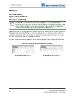
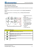
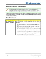
Unit [n] > Show Instrument Schematic
Use to enable the manual control of certain system valves and pump components on the analyzer
schematic.
When this option is enabled, a checkmark appears to the left of
Unit [n] > Enable Manual
Control
.
If the analyzer schematic is not immediately visible, go to
Unit [n] > Show Instrument
Schematic
.
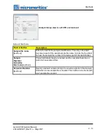
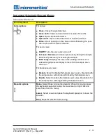
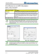
A. Differential pressure trans-
ducer
B. Balance tube
C. Balance volume adjustment
D. Balance tube reservoir
E. Quantity adsorbed trans-
ducer
F. Sample tube reservoir
G. P
̀o
tube, valve, and trans-
ducer reading are not dis-
played on Model 2390a
H. Sample tube
I. Elevator
J. Pressure relief valve
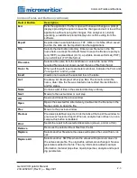
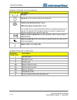
Icon or Symbol Description
Open Valve
. Green indicates an open valve.
Closed Valve
. Yellow indicates a closed valve. When manual control is
disabled, closed valves appear white.
Servo Valve
. Closed.
Servo Valve
. Open.
Analyzer Schematic Icons
Show Instrument Schematic
Gemini VII Operator Manual
239-42828-01 (Rev H ) — May 2021
2 - 17
Summary of Contents for GEMINI VII
Page 1: ...OPERATOR MANUAL 239 42828 01 May 2021 Rev H GEMINI VII SURFACE AREA ANALYZER ...
Page 10: ......
Page 16: ......
Page 92: ......
Page 126: ...6 About Reports SAMPLE LOG REPORT 6 34 Gemini VII Operator Manual 239 42828 01 Rev H May 2021 ...
Page 127: ...T PLOT REPORT t Plot Report Gemini VII Operator Manual 239 42828 01 Rev H May 2021 6 35 ...
Page 128: ...6 About Reports VALIDATION REPORT 6 36 Gemini VII Operator Manual 239 42828 01 Rev H May 2021 ...
Page 234: ......
Page 242: ......
Page 244: ......
Page 247: ......
Page 248: ......


