


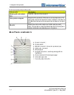
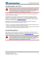


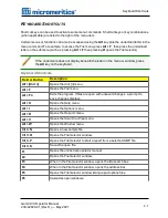

1 Analyzer Components
Components
Description
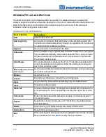
Sample port and sample
tube
Holds the material to be analyzed.
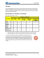
Tube position diagram
Diagram of the positions of the balance and sample tubes. The
empty tube represents the balance tube installed on the left port.
The filled tube represents the sample tube installed on the right
port.
Elevator
Allows placement of the Dewar around the sample and P
0
tubes. The elevator is raised automatically when the analysis is
started and lowers automatically upon completion.
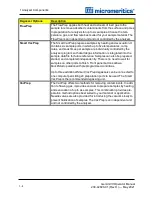
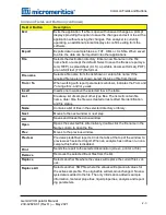
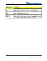
Front Components (continued)
B
ACK
P
ANEL COMPONENTS
A. Power connector
B. Power switch
C. RS232 connector - for service personnel use
D. USB ports - not used
E. Ethernet port
F. Keypad connection - used only wit keypad con-
figurations
G. Helium inlet port for helium gas supply
H. Adsorptive gas inlet
I. Vacuum pump connector
1 - 2
Gemini VII Operator Manual
239-42828-01 (Rev H ) — May 2021
Summary of Contents for GEMINI VII
Page 1: ...OPERATOR MANUAL 239 42828 01 May 2021 Rev H GEMINI VII SURFACE AREA ANALYZER ...
Page 10: ......
Page 16: ......
Page 92: ......
Page 126: ...6 About Reports SAMPLE LOG REPORT 6 34 Gemini VII Operator Manual 239 42828 01 Rev H May 2021 ...
Page 127: ...T PLOT REPORT t Plot Report Gemini VII Operator Manual 239 42828 01 Rev H May 2021 6 35 ...
Page 128: ...6 About Reports VALIDATION REPORT 6 36 Gemini VII Operator Manual 239 42828 01 Rev H May 2021 ...
Page 234: ......
Page 242: ......
Page 244: ......
Page 247: ......
Page 248: ......


