Switching the AC Power
Appendix A
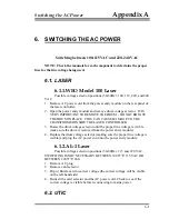
6. SWITCHING THE AC POWER
Switching between 100-115VAC and 220-240 VAC
NOTE: Check the manuals for each component to determine the proper
fuse for the line voltage being used.
6.1. LASER
6.1.1.WEO Model 100 Laser
Possible voltage selection positions (50-60Hz): 100, 115, 220, and 240
VAC
1. Remove AC power cord from the power entry module on the rear panel of
the laser controller.
2. Open the power entry module and remove drum voltage selector. IT IS
VERY IMPORTANT TO REMOVE THE DRUM - DO NOT ROTATE
THE DRUM IN PLACE. THIS CAN CAUSE DAMAGE TO THE
TRANSFORMER INSIDE THE LASER CONTROLLER.
3. Rotate the drum voltage selector until the proper line voltage is visible
(make sure the drum is removed from the power entry module).
4. Replace the drum voltage selector (making sure the proper line voltage is
visible) and plug the AC power cord into the power entry module.
6.1.2.AL-1 Laser
Possible voltage selection positions (50-60Hz): 115 and 220 VAC.
SWITCHING IS NOT NECESSARY BETWEEN 100
ÅÆ
115 VAC OR
BETWEEN 220
ÅÆ
240.
1. Remove AC plug
2. Remove card selector
3. Flip or Rotate card to correct voltage (the correct voltage will be visible
on the left-hand side)
4. Reinsert the card selector and the AC power cord. Check to see if the
correct voltage is visible before reconnecting to mains power.
6-1
6.2. UTIC
Summary of Contents for FG5
Page 22: ...Design Components and Function 2 Figure 2 10 The Superspring 2 14 ...
Page 31: ...Design Components and Function 2 Figure 2 13 Rotation Monitor 2 23 ...
Page 32: ......
Page 42: ...How to Set Up and Run the FG5 3 3 10 ...
Page 44: ...How to Set Up and Run the FG5 3 Figure 3 2 V Post 3 12 ...
Page 53: ...How to Set Up and Run the FG5 3 1 Backup the data 2 Shut off computer power 3 21 ...
Page 87: ...Adjustment and Maintenance 4 4 29 ...
Page 91: ...Adjustment and Maintenance 4 4 33 ...
Page 104: ...Troubleshooting 5 5 2 ...
Page 117: ...Troubleshooting 5 5 15 ...
Page 131: ...Checklists and Logs Appendix D 9 3 ...
Page 140: ...Checklists and Logs Appendix D Table 9 6 Replacing Drive Belt 9 12 ...
Page 145: ...Checklists and Logs Appendix D Table 9 10 Replace Linear Bearings 9 17 ...
Page 149: ...Checklists and Logs Appendix D Table 9 13 Replace Shaft Encoder 9 21 ...


