Design: Components and Function
2
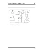
The rotation monitor (Figure 2-13) is used to monitor and record the rotation
of the test mass during each drop. The rotation monitor consists of a rigid
anodized aluminum housing mounted on the top flange of the dropping
chamber, above the viewing port. The rotation monitor employs a very
sensitive optical lever system to measure and record the rotation of the test
mass which can be used as a means to reject bad drops or determine when the
mechanical system is not functioning properly. A diode laser produces a
visible beam which is directed onto and reflects from a mirror attached to the
top of the dropped object. The reflected beam is sent through a lens and is
focused onto a two axis position sensitive photodetector. This system rejects
translation and is only sensitive to rotation. The diode laser beam reflects off
mirror #1 and the beamsplitter (mirror mount #2). The beam then passes
down through the dropping chamber viewing port, where it reflects off a flat
mirror which is mounted to the top of the test mass. The return beam from
the test mass mirror passes through the beamsplitter and reflects off mirror
#3. The beam then passes through the 200 mm focusing lens, which is
adjusted to eliminate cross coupling of translations which would otherwise
appear as rotations. The beam is then reflected off mirror #4 and enters the
detector box. The output from the quad detector is used to provide rotation
information to the computer/system controller. Each rotation monitor is
calibrated by Micro-g Solutions to determine the rotation and translation
sensitivity. These data are used to calculate rotation errors. The rotation data
can also be displayed on the computer screen, and is recorded in the DDT
output data file.
2-22
Summary of Contents for FG5
Page 22: ...Design Components and Function 2 Figure 2 10 The Superspring 2 14 ...
Page 31: ...Design Components and Function 2 Figure 2 13 Rotation Monitor 2 23 ...
Page 32: ......
Page 42: ...How to Set Up and Run the FG5 3 3 10 ...
Page 44: ...How to Set Up and Run the FG5 3 Figure 3 2 V Post 3 12 ...
Page 53: ...How to Set Up and Run the FG5 3 1 Backup the data 2 Shut off computer power 3 21 ...
Page 87: ...Adjustment and Maintenance 4 4 29 ...
Page 91: ...Adjustment and Maintenance 4 4 33 ...
Page 104: ...Troubleshooting 5 5 2 ...
Page 117: ...Troubleshooting 5 5 15 ...
Page 131: ...Checklists and Logs Appendix D 9 3 ...
Page 140: ...Checklists and Logs Appendix D Table 9 6 Replacing Drive Belt 9 12 ...
Page 145: ...Checklists and Logs Appendix D Table 9 10 Replace Linear Bearings 9 17 ...
Page 149: ...Checklists and Logs Appendix D Table 9 13 Replace Shaft Encoder 9 21 ...


