


Adjustment and Maintenance
4
This step assumes that the tripod levels have been set so that level ensures
that the cart travel is vertical. Now we will adjust the interferometer so that it
is referenced to the tripod tray bubble levels that were set in the last step. This
next adjustment will ensure that the beam is vertical and travels cleanly
through the dropper when the dropper and tripod are sitting on the
interferometer base with the bubble levels indicating level. Mirrors #3 and #4
will be used to translate the beam so that it enters and exits the dropper
without clipping on the tubes of the drag free chamber. Another requirement
is that the beam is also traveling vertically into and out of the dropping
chamber. Although both mirrors translate and tilt the beam, it is good to first
use mirror #3 as the translation mirror and #4 to adjust the verticality of the
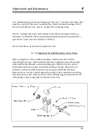
beam during the alignment procedure. First, lower the tripod/dropper onto
the interferometer base. Level the interferometer base until the levels on the
tripod/dropper are centered. Put a dish of alcohol on the floor below the
interferometer base. Hold a white card over the dish of alcohol and adjust
mirror #3 (farthest from the first beamsplitter) until the beam is traveling
through the dropper system cleanly. Remove the card and look into the
telescope and you will see the reference beam and the return beam from the
alcohol dish. Adjust mirror #4 until they overlap in the telescope (this adjusts
the verticality of the beam). [DO NOT ADJUST THE LEGS OF THE
INTERFEROMETER BASE- WE WANT TO LEAVE THE INTERFEROMETE
BASE REFERENCED TO THE BUBBLE LEVELS] Since this procedure may
also cause the beam to translate, it is often necessary to iterate the procedure
of translation using mirror #3 and aligning with the beam with vertical using
mirror #4. This procedure converges rather slowly and takes about 10
iterations.
4.2.2.12.Adjusting the Superspring position and final
adjustment mirror
4-15
The Superspring position must be set so that the test-beam returns cleanly
after going into and out of the Superspring. In addition, it is important to get
the reference and test beams to overlap in the fringe viewer when the
translator plate underneath the interferometer base (twiddler) is in the mid-
range position. It may be necessary to adjust the position of the Superspring
interface plate (top mounting plate) that attaches to the bottom of the
interferometer and supports the Superspring chamber. The five M5 screws
Summary of Contents for FG5
Page 22: ...Design Components and Function 2 Figure 2 10 The Superspring 2 14 ...
Page 31: ...Design Components and Function 2 Figure 2 13 Rotation Monitor 2 23 ...
Page 32: ......
Page 42: ...How to Set Up and Run the FG5 3 3 10 ...
Page 44: ...How to Set Up and Run the FG5 3 Figure 3 2 V Post 3 12 ...
Page 53: ...How to Set Up and Run the FG5 3 1 Backup the data 2 Shut off computer power 3 21 ...
Page 87: ...Adjustment and Maintenance 4 4 29 ...
Page 91: ...Adjustment and Maintenance 4 4 33 ...
Page 104: ...Troubleshooting 5 5 2 ...
Page 117: ...Troubleshooting 5 5 15 ...
Page 131: ...Checklists and Logs Appendix D 9 3 ...
Page 140: ...Checklists and Logs Appendix D Table 9 6 Replacing Drive Belt 9 12 ...
Page 145: ...Checklists and Logs Appendix D Table 9 10 Replace Linear Bearings 9 17 ...
Page 149: ...Checklists and Logs Appendix D Table 9 13 Replace Shaft Encoder 9 21 ...