


Adjustment and Maintenance
4
4.4.1.3.Scaler-Counter Printed Circuit Board
The scaler-counter board has several major functional blocks:
1.
Clock discriminator
2.
Clock
scaling
3.
Scaled clock count accumulator
4.
Fringe
scaling
5.
Scaled fringe accumulator
6.
Accumulator/computer data latching
7.
Miscellaneous I/O interface circuitry
The incoming clock signal is converted to TTL levels (1), and then scaled (2)
according to a three-digit hexadecimal value selected with three PCB hex
switches. The scaled clock output of this circuit increments the 10-bit clock
accumulator (3) and is also sent to the UTIC via a BNC connector on the front
panel. Except that it does not need a TTL discriminator, the fringe scaling
circuit (4) is identical to that of the clock scaler. The scaled fringes are
counted by a 4-bit accumulator (5), and are passed on to the UTIC via a front
panel BNC connector.
The leading edge of the latch pulse from the UTIC latches (6) the current
values of the scaled clock and fringe accumulators into buffers, along with the
states of the "data_valid" and "up/down" status lines. The accumulators
themselves are then cleared by the trailing edge of the delayed latch. To
indicate data available for reading, an extended latch pulse is sent to the
computer.
A control line from the computer, /DIS, disables the fringe output to the
UTIC so that an incoming fringe cannot retrigger the UTIC until after the
computer has finished its current data read operation.
4-28
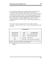
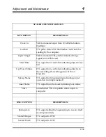
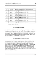
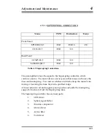
Several other signals are routed to and from the computer through the scaler-
counter board. They are specified in Table 4-2.
Summary of Contents for FG5
Page 22: ...Design Components and Function 2 Figure 2 10 The Superspring 2 14 ...
Page 31: ...Design Components and Function 2 Figure 2 13 Rotation Monitor 2 23 ...
Page 32: ......
Page 42: ...How to Set Up and Run the FG5 3 3 10 ...
Page 44: ...How to Set Up and Run the FG5 3 Figure 3 2 V Post 3 12 ...
Page 53: ...How to Set Up and Run the FG5 3 1 Backup the data 2 Shut off computer power 3 21 ...
Page 87: ...Adjustment and Maintenance 4 4 29 ...
Page 91: ...Adjustment and Maintenance 4 4 33 ...
Page 104: ...Troubleshooting 5 5 2 ...
Page 117: ...Troubleshooting 5 5 15 ...
Page 131: ...Checklists and Logs Appendix D 9 3 ...
Page 140: ...Checklists and Logs Appendix D Table 9 6 Replacing Drive Belt 9 12 ...
Page 145: ...Checklists and Logs Appendix D Table 9 10 Replace Linear Bearings 9 17 ...
Page 149: ...Checklists and Logs Appendix D Table 9 13 Replace Shaft Encoder 9 21 ...