


Adjustment and Maintenance
4
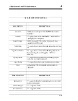
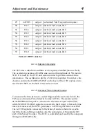
Throw Init
TTL control line to controller used to initiate a
throw cycle
Laser Control
TTL signal to laser controller used to indicate
which mode to lock (red or blue)
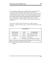
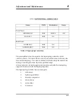
Table 4-2 Scaler Counter Signals
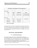
DB-37 CONNECTOR SIGNALS TO COMPUTER
PIN NAME TYPE
DESCRIPTION
3
FL3
output latched fringe count, bit 3
4
FL2
output latched fringe count, bit 2
5
FL1
output latched fringe count, bit 1
6
FL0
output latched fringe count, bit 0
7
VALIDL
output latched "data valid" status bit
8
U/D_L
output latched "up/down" status bit
9
DL9
output latched clock count, bit 9
10
DL8
output latched clock count, bit 8
17 GND power
ground
connection
19 GND power
ground
connection
21 GND power
ground
connection
22
CTL1
input laser control signal
23
CTL0
input spring zero signal
24
/DIS
input fringe output inhibit
25
INIT
input throw init signal; also clears clock and
fringe count accumulators
26
STAT2
output undedicated "status input 2" bit
27
laser stat
output undedicated "status input 1" bit
28
SPRINSTAT output spring status bit
4-31
Summary of Contents for FG5
Page 22: ...Design Components and Function 2 Figure 2 10 The Superspring 2 14 ...
Page 31: ...Design Components and Function 2 Figure 2 13 Rotation Monitor 2 23 ...
Page 32: ......
Page 42: ...How to Set Up and Run the FG5 3 3 10 ...
Page 44: ...How to Set Up and Run the FG5 3 Figure 3 2 V Post 3 12 ...
Page 53: ...How to Set Up and Run the FG5 3 1 Backup the data 2 Shut off computer power 3 21 ...
Page 87: ...Adjustment and Maintenance 4 4 29 ...
Page 91: ...Adjustment and Maintenance 4 4 33 ...
Page 104: ...Troubleshooting 5 5 2 ...
Page 117: ...Troubleshooting 5 5 15 ...
Page 131: ...Checklists and Logs Appendix D 9 3 ...
Page 140: ...Checklists and Logs Appendix D Table 9 6 Replacing Drive Belt 9 12 ...
Page 145: ...Checklists and Logs Appendix D Table 9 10 Replace Linear Bearings 9 17 ...
Page 149: ...Checklists and Logs Appendix D Table 9 13 Replace Shaft Encoder 9 21 ...