


Page 111
Line Scanner Mode
thermoIMAGER TIM Connect
If more than one line should be taken from the source the
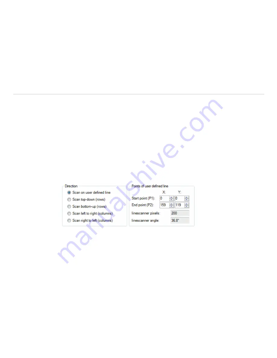
Direction
menu enables to choose the direction
in which they will be measured and consequently displayed in
Line scanner sighting view
mode.
The option
Scan on user defined line
makes it possible to graphically position the scan line through
the mouse. It can also be entered by the coordinates (X and Y) in the
Start point (P1)
and
End point
(P2)
fields. The number of pixels on the scan line and the angle are displayed in the field
linescanner
pixels
and
linescanner angle
. In addition to the start and end point, additional points can be added
under
Add
, allowing complex lines to be created.
Lines
or
Splines
can be used.
The other options you can choose from are
Scan top-down (rows)
where the lines are measured and
displayed from the top to the bottom,
Scan bottom-up (rows)
from bottom to top,
Scan left to
right (columns)
from left to right and Scan right to left (columns) from right to left.
In all direction variants the scan line can be moved by mouse.
In the
Scan on user defined line
, individual points are moved by drag-n-drop.
The entire scan line is moved by touching a point with the Ctrl key pressed at the same time.
A rotation is reached when first a point is selected with simultaneous pressing the Alt key (this is the pivot
point) and then a second point is drawn to rotate the line.
Fig. 113 View Direction
Fig. 114 View Points of user defined line


