background image

5.  Voltmeter

5.1   TRMS (True RMS)

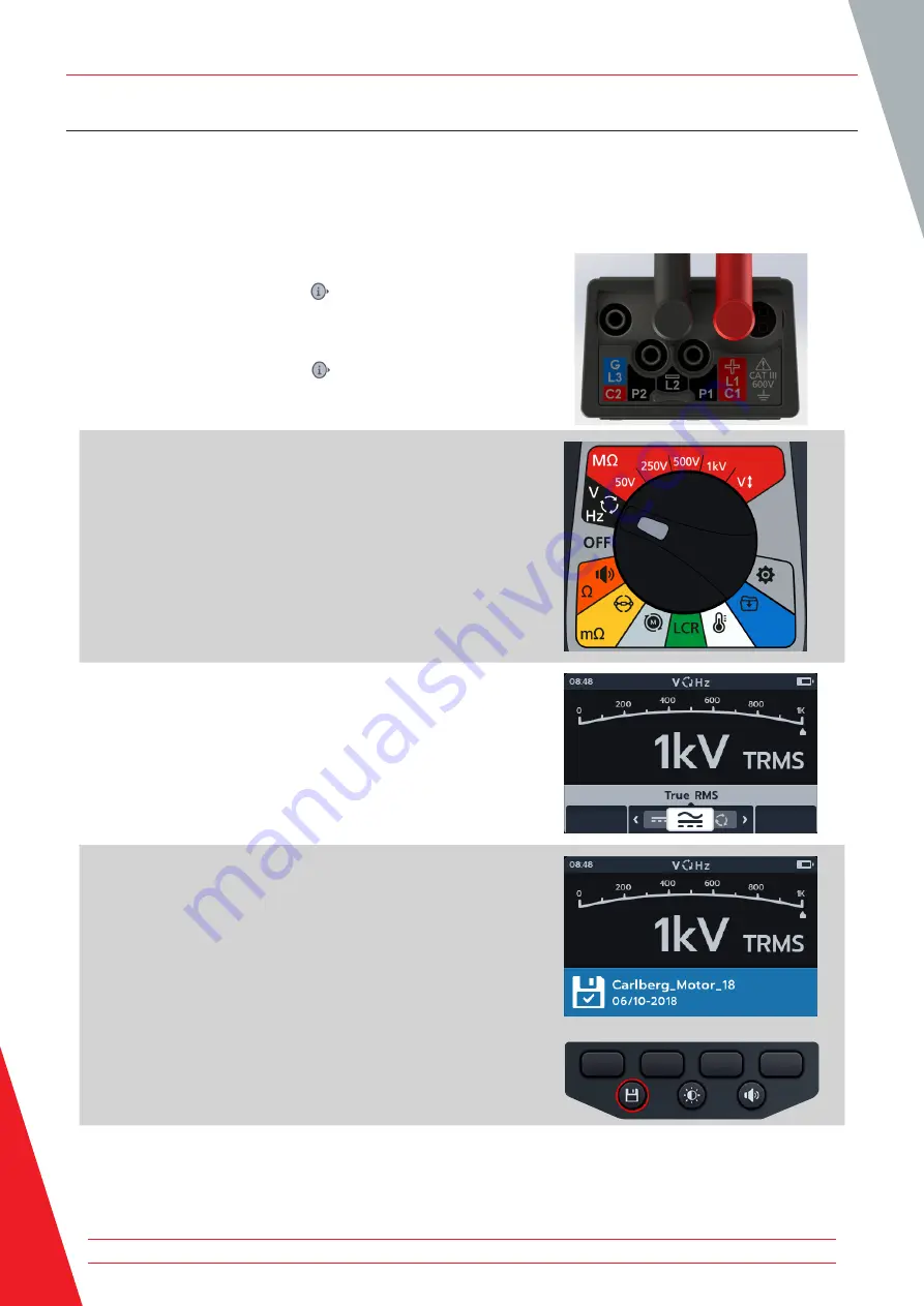
Default is TRMS mode shows true RMS voltage. In TRMS mode the MTR105 will measure both ac and dc components 
of the supply voltage (ac+dc).

1.  Connect the test leads to the MTR105.

1.1.  Press the Information (

) button to view the lead set 

up diagram.

NOTE: 

When the diagram is displayed a test cannot be 

performed.  Press Information 

(

)

 button to return to the test 

screen.

2.  Turn rotary switch to select Voltmeter (V) position.

3.  The TRMS test starts automatically.
4.  During the tests, 


ƒ

The primary field displays the measured voltage.


ƒ

The secondary field displays frequency.

5.  The result can be saved by pressing the SAVE button.  A 

message will inform you the data was saved and which asset 
ID it was saved to.

Voltmeter

28  

www.megger.com

Summary of Contents for MTR105

Page 1: ...Baker Instruments MTR105 Rotating Machine Tester User Guide ...

Page 2: ...e right to alter the specification of its products from time to time without notice Although every effort is made to ensure the accuracy of the information contained within this document it is not warranted or represented by Megger Ltd to be a complete and up to date description For Patent information about this instrument refer to the following web site http uk megger com patents ...

Page 3: ...imited described in this user guide is in compliance with Directives 2014 30 EU and 2014 35 EU where they apply The full text of Megger Instruments EU declarations of conformity are available at the following internet address uk megger com company about us eu dofc www megger com iii This manual supersedes all previous issues of this manual Please ensure that you are using the most recent issue of ...

Page 4: ... 6 2 4 Company web site 6 2 5 Instrument Controls 7 2 6 Instrument Display 8 2 7 Instrument Controls 9 2 8 Instrument Connections and Leads 10 2 8 1 View on top of MTR105 10 3 Instrument Set up 11 3 1 Warnings and exception conditions 11 3 2 Power 11 3 2 1 First use 11 3 2 2 Turn the instrument on and off 11 3 2 3 Power options 12 3 3 Lockout Voltage 12 4 Insulation Resistance Tests 13 4 1 Insulat...

Page 5: ... Direction of Motor Rotation 47 9 Inductance L Capacitance C Resistance R LCR 48 9 1 Auto 48 9 2 Capacitance or inductance 49 9 3 LCR Calibration 51 10 Temperature measurement 54 10 1 Thermocouple temperature measurement 54 10 2 Manual Temperature measurement 56 11 Data management 58 11 1 Creating a new asset ID 58 11 2 Using an existing asset ID 59 11 3 Deleting an asset 60 11 4 Deleting items fr...

Page 6: ...settings 75 14 3 Language settings 75 15 Maintenance 76 15 1 General Maintenance 76 15 2 Cleaning 76 15 3 Battery 76 15 3 1 Battery status 76 15 3 2 12 V supply 77 15 3 3 Battery Charging 77 15 3 4 Battery error screens 77 15 4 Battery and Fuse Replacement 78 15 4 1 Replace battery cells and remove isolation tab 79 15 4 2 To replace the fuses 79 16 Specifications 80 17 Accessories and Equipment 83...

Page 7: ... www megger com vii ...

Page 8: ...people Protection provided by the instrument may be impaired if it is not used in a manner specified by the manufacturer Local Health and Safety Legislation requires users of this equipment and their employers to carry out valid risk assessments of all electrical work to identify potential sources of electrical danger and risk of electrical injury such as inadvertent short circuits Where the asses...

Page 9: ...ocodile clips must be in good condition clean dry and free of broken or cracked insulation The lead set or its components must not be used if any part of it is damaged The safe maximum limit of a measurement connection is that of the lowest rated component in the measurement circuit formed by the instrument test leads and any accessories The CAT III 600 V rated thermocouple probe tip and protectiv...

Page 10: ...cons This section details the warning icons that can show on the display Icon Warning Description F External Voltage Warning If an external voltage is applied between the terminals and the instrument is set to On the High Voltage warning will flash on the display This is a warning that the item under test is live and might be dangerous and testing is disabled The High Voltage warning message will ...

Page 11: ...ons for all MTR105 variants Some facilities may not be available on your model of this equipment The MTR105 takes the test abilities of Megger s proven MIT400 test instruments adding DLRO four wire tests inductance and capacitance to provide a versatile motor tester all packaged in a robust hand held instrument which up to now has simply not been available In addition the MTR105 also incorporates ...

Page 12: ...fferent applications Stores test results for up to 256 motors which can be downloaded to a USB drive Rotary dial control and full graphic display simple and easy to use Sealed to IP54 providing protection against moisture and dust ingress including the battery and fuse compartments Tough housing A rubber over moulding combines a tough shock absorbing outer protection with excellent grip on a stron...

Page 13: ... 7 9 Item Description Item Description 1 External electrical connections 6 Save 2 Display 7 Test 3 Soft keys multifunction 8 Information Lock OK 4 Buzzer control 9 Rotary selection switch 5 Back light control Introduction www megger com 7 ...

Page 14: ...strument Display 7 1 2 5 6 3 4 Item Description Item Description 1 Status Mode 5 Soft key functions 2 Battery indicator 6 Secondary field 3 Primary field 7 Time 4 Status symbols Introduction 8 www megger com ...

Page 15: ...ack 3 Temperature White 10 Insulation Resistance Test 50 V Red 4 Inductance capacitance and resistance Green 11 Insulation Resistance Test 250 V Red 5 Motor direction of rotation Light grey 12 Insulation Resistance Test 500 V Red 6 Digital Low Resistance Ohmmeter Yellow 13 Insulation Resistance Test 1 kV Red 7 Continuity and diode test Orange 14 Insulation Resistance Test user selectable voltage R...

Page 16: ...ons are all situated on top of the MTR105 A sliding cover is installed to prevent any other connection being made at the same time as the USB port Connection to the USB port can only be made when the sliding cover is pushed completely to the back of the instrument For charging or connection to any test leads the sliding cover must be in the forward position The charger connection is designed so th...

Page 17: ...05 can be turned on the battery isolation tab must be removed 1 Remove the battery cover 2 Pull the battery isolation tab clear of the battery cells 3 Replace cover For further details on accessing the battery panel Refer to 15 4 Battery and Fuse Replacement on page 78 For initial date and time set up Refer to 14 2 3 Date on page 74 and Refer to 14 2 7 Time on page 75 NOTE If the MTR should lose t...

Page 18: ...o NiMh Warning Charge NiMH cells only between 0 ºC and 40 ºC ambient The battery cell type is selected from the settings menu Refer to 14 Settings on page 71 It will not charge Alkaline or LiFeS2 cells To charge the cells in the instrument it has to have the mains charger kit plugged into the terminal connections Testing or access the USB is not possible while the instrument is being charged See a...

Page 19: ...Dielectric Absorption Ratio it is the ratio between the insulation resistance values at 15 or 30 seconds assigned t1 and at 60 second interval assigned t2 i e after 30 seconds and 60 seconds DAR 15 or 30 default second value 60 second value T s Time IR Selectable from 1 minute to 10 minutes in 1 minute increments 3P 3 Phase To test insulation resistance phase to phase FThis warning triangle flashe...

Page 20: ...in and the buzzer sounds for a second 4 4 Insulation Resistance IR Test 1 Connect the test leads to the MTR105 1 1 Press the Information button to view the lead set up diagram NOTE when the diagram is displayed a test cannot be performed Press Information button to return to the test screen This test can also be performed with just the red and the black lead 2 Connect the test leads to the unit un...

Page 21: ...n page 16 NOTE This is only available in IR test mode To adjust the insulation threshold Refer to 14 Settings on page 71 8 Start the test by pressing and holding down the TEST button The buzzer will sound on test initiation 8 1 To hold the test voltage press the LOCK button while the TEST button is held Once the lock symbol is displayed and the buzzer has sounded the TEST button can be released Th...

Page 22: ...result press the SAVE button A message will inform you the data was saved and which asset ID it was saved to 13 To restart the test press the TEST button again NOTE To set up an asset ID Refer to 14 Settings on page 71 4 4 1 Buzzer settings Set the buzzer to the preferred option before starting a test Buzzer status is indicated at the bottom right hand corner of the primary field The buzzer thresh...

Page 23: ...n green 4 4 2 Temperature compensation NOTE Temperature compensation is only available in IR sub mode Temperature compensation is off by default Before an insulation resistance test can be carried out with temperature compensation enabled the temperature of the unit under test must be established For this procedure Refer to 14 1 4 Temperature compensation on page 72 If a temperature measurement ha...

Page 24: ... when the diagram is displayed a test cannot be performed Press Information button to return to the test screen 2 Connect the test leads to the unit under test NOTE The connection is for illustrative purposes only When performing phase to phase measurements the star or delta configuration has to be disconnected 3 Select the required insulation test voltage 4 The display will show the selected volt...

Page 25: ...en NOTE The test can be stopped at any time by pressing the TEST button 7 During the tests The primary field displays the test results and the active and completed phase to phase tests in the three phase sequence The secondary field displays actual voltage output and the current measured 8 When the test has completed The primary field displays the test results and also the actual voltage output an...

Page 26: ...e Information button to view the lead set up diagram NOTE when the diagram is displayed a test cannot be performed Press Information button to return to the test screen This test can also be performed with just the red and the black lead 2 Connect the test leads to the unit under test NOTE The connection is for illustrative purposes only When performing phase to phase measurements the star or delt...

Page 27: ... will appear in the bottom left of the primary screen The test will continue for 10 minutes The clock will countdown the test An interval result will appear after 1 minute A warning triangle will flash on screen NOTE The test can be stopped at any time by pressing the TEST button 7 During the tests The primary field displays the test results The secondary field displays actual voltage output and t...

Page 28: ...Information button to view the lead set up diagram NOTE When the diagram is displayed a test cannot be performed Press Information button to return to the test screen This test can also be performed with just the red and the black lead 2 Connect the test leads to the unit under test NOTE The connection is for illustrative purposes only When performing phase to phase measurements the star or delta ...

Page 29: ...e Timed test is user configurable and can run for 1 2 3 4 5 6 7 8 9 or 10 minutes Refer to 14 1 6 Timed Insulation on page 73 A warning triangle will flash on screen NOTE The test can be stopped at any time by pressing the TEST button 7 During the tests The primary field displays the test results The secondary field displays actual voltage output and the current measured 8 When the test has comple...

Page 30: ...w the lead set up diagram NOTE when the diagram is displayed a test cannot be performed Press Information button to return to the test screen This test can also be performed with just the red and the black lead 2 Connect the test leads to the unit under test NOTE The connection is for illustrative purposes only When performing phase to phase measurements the star or delta configuration has to be d...

Page 31: ...ppear in the bottom left corner of the primary field as the DAR test runs for one minute A warning triangle will flash on screen NOTE The test can be stopped at any time by pressing the TEST button 7 During the tests The primary field displays the test results The secondary field displays actual voltage output and the current measured 8 When the test has completed The primary field displays the te...

Page 32: ...Connect the test leads to the MTR105 2 1 Press the Information button to view the lead set up diagram NOTE when the diagram is displayed a test cannot be performed Press Information button to return to the test screen This test can also be performed with just the red and the black lead 3 Connect the test leads to the unit under test NOTE The connection is for illustrative purposes only When perfor...

Page 33: ...n this case 10 V 6 Press soft keys 2 and 3 to move the carousel left or right through sub modes IR is default scroll through to 3P PI T s DAR 7 Run the chosen test as described in the previous sections Insulation Resistance Tests www megger com 27 ...

Page 34: ...OTE When the diagram is displayed a test cannot be performed Press Information button to return to the test screen 2 Turn rotary switch to select Voltmeter V position 3 The TRMS test starts automatically 4 During the tests The primary field displays the measured voltage The secondary field displays frequency 5 The result can be saved by pressing the SAVE button A message will inform you the data w...

Page 35: ...Voltmeter V position 3 Press soft keys 2 and 3 to move the carousel left or right through sub modes to ac or dc as required NOTE The full title text of the sub mode will appear in the secondary field for a few seconds 4 The ac and dc tests start automatically 5 During the ac tests The primary field displays the measured voltage The secondary field displays frequency 6 During the dc tests The prima...

Page 36: ...ton to view the lead set up diagram NOTE when the diagram is displayed a test cannot be performed Press Information button to return to the test screen 2 Turn rotary switch to select Voltmeter V position 3 Press soft keys 2 and 3 to move the carousel left or right through sub modes to Supply Phase Rotation NOTE The full title text of the sub mode will appear in the secondary field for a few second...

Page 37: ...The primary field displays the phase rotation sequence of the supply and constantly updating results for each phase sequence of the supply The secondary field displays frequency 6 The result can be saved by pressing the SAVE button A message will inform you the data was saved and which asset ID it was saved to Voltmeter www megger com 31 ...

Page 38: ...d set up diagram NOTE When the diagram is displayed a test cannot be performed Press Information button to return to the test screen 2 Turn rotary switch to select Continuity position 3 If required Turn the buzzer on off or visual as required by pressing buzzer button NOTE This is only available in uni direction mode 4 To adjust the threshold press soft key 4 NOTE The buzzer mode bypasses the cont...

Page 39: ...he full title text of the sub mode will appear in the secondary field for a few seconds 8 The test current can be toggled between 200 mA and 20 mA pressing soft key 1 9 NULL the test leads by touching the two test probe ends Press the TEST button until the NULL symbol appears on the screen The ohmic value on the primary screen will read 0 Ω 10 Connect the test leads to the unit under test NOTE The...

Page 40: ...irection 1 Connect the test leads to the MTR105 1 1 Press the Information button to view the lead set up diagram NOTE When the diagram is displayed a test cannot be performed Press Information button to return to the test screen 2 Turn rotary switch to select Continuity position 3 Press soft keys 2 and 3 to move the carousel left or right through sub modes to bi direction NOTE The full title text ...

Page 41: ...the test leads to the unit under test NOTE The connection is for illustrative purposes only showing winding resistance across phase 1 7 This test starts automatically 8 During the tests The primary field displays the result of the true resistance of the unit under test The secondary field displays the test current and the resistance values in both directions highest value shown in Primary The test...

Page 42: ...lly 5 During the tests the primary field displays the voltage drop as it is measured A good forward biased diode displays a voltage drop ranging from 0 5 to 0 8 V for the most commonly used silicon diodes Some germanium diodes have a voltage drop ranging from 0 2 to 0 3 V The voltage drop is also dependent on the test current The meter displays O C when a good diode is reverse biased The O C readi...

Page 43: ...ound and the background will not flash the display will show OL NOTE The user is responsible for connecting test probes across the diode under test There is no information displayed in the secondary field at this point The only information to display is the diode drop voltage if the instrument senses a voltage across the device If no current flows the main display will show O C Continuity www megg...

Page 44: ...ormation button to return to the test screen 2 Connect the test leads to the unit under test NOTE The connection is for illustrative purposes only showing winding resistance across phase 1 3 Turn rotary switch to select the DLRO mΩ position 4 Press soft keys 3 to choose the sub mode uni directional NOTE The full title text of the sub mode will appear in the secondary field for a few seconds DLRO D...

Page 45: ...e primary field displays the result with the actual current being delivered As the resistance gets higher the current will get lower The secondary field displays the continuity on the Current C1 C2 and potential P1 P2 circuits 9 The result can be saved by pressing the SAVE button A message will inform you the data was saved and which asset ID it was saved to 10 To restart the test press the TEST b...

Page 46: ...eturn to the test screen 2 Connect the test leads to the unit under test NOTE The connection is for illustrative purposes only showing winding resistance across phase 1 3 Turn rotary switch to select the DLRO mΩ position 4 Press soft keys 3 to choose the sub mode uni directional NOTE The full title text of the sub mode will appear in the secondary field for a few seconds DLRO Digital Low Resistanc...

Page 47: ...rrent will get lower The secondary field displays the continuity on the Current C1 C2 and potential P1 P2 circuits 9 The result can be saved by pressing the SAVE button A message will inform you the data was saved and which asset ID it was saved to 10 To restart the test re connect to a new test piece and the test will start automatically 7 3 Manual bi direction test 1 Connect the test leads to th...

Page 48: ...ct the DLRO mΩ position 4 Press soft keys 2 to choose the sub mode bi directional NOTE The full title text of the sub mode will appear in the secondary field for a few seconds 5 If there is a continuity reading detected for C and P connections the secondary fields will display with a tick and background will be green DLRO Digital Low Resistance Ohmmeter 42 www megger com ...

Page 49: ...rcuits 9 When the test has completed The primary field displays the result for current and resistance in each direction and an average of the two The secondary field displays the continuity on the Current C1 C2 and potential P1 P2 circuits 10 The result can be saved by pressing the SAVE button A message will inform you the data was saved and which asset ID it was saved to 11 To restart the test pr...

Page 50: ...urn to the test screen 2 Connect the test leads to the unit under test NOTE The connection is for illustrative purposes only showing winding resistance across phase 1 3 Turn rotary switch to select the DLRO mΩ position 4 Press soft keys 2 to choose the sub mode bi directional NOTE The full title text of the sub mode will appear in the secondary field for a few seconds DLRO Digital Low Resistance O...

Page 51: ...condary field displays the continuity on the Current C1 C2 and potential P1 P2 circuits 9 When the test has completed The primary field displays the result for current and resistance in each direction and an average of the two The secondary field displays the continuity on the Current C1 C2 and potential P1 P2 circuits 10 The result can be saved by pressing the SAVE button A message will inform yo...

Page 52: ...ction be lost during the test the MTR105 will notify the user The user can re make the connection then restart the test after a few seconds by pressing the test button or by reconnecting to a test piece DLRO Digital Low Resistance Ohmmeter 46 www megger com ...

Page 53: ...iagram is displayed a test cannot be performed Press Information button to return to the test screen 2 Connect the test leads to the unit under test NOTE The connection is for illustrative purposes only 3 Turn rotary switch to select direction of motor rotation position 4 Rotate the motor in one direction Check if display matches L1 L2 L3 correct phases of rotation 5 Rotate the motor in opposite d...

Page 54: ...yed a test cannot be performed Press Information button to return to the test screen 2 Connect the test leads to the unit under test NOTE The connection is for illustrative purposes only showing connection across phase 1 3 Turn rotary switch to select the LCR position 4 Press soft keys 2 and 3 to move the carousel left or right through sub modes to auto capacitance inductance test NOTE The full ti...

Page 55: ...sult for the reactive component This could be capacitance inductance or resistance The secondary field displays the frequency 9 2 Capacitance or inductance 1 Connect the test leads to the MTR105 1 1 Press the Information button to view the lead set up diagram NOTE When the diagram is displayed a test cannot be performed Press Information button to return to the test screen Inductance L Capacitance...

Page 56: ...t the LCR position 4 Press soft keys 2 and 3 to move the carousel left or right through sub modes to capacitance or inductance test NOTE The full title text of the sub mode will appear in the secondary field for a few seconds capacitance inductance 5 Press soft keys 1 to toggle between 120 Hz and 1000 Hz Inductance L Capacitance C Resistance R LCR 50 www megger com ...

Page 57: ...ing the tests The primary field displays the result for the reactive component This could be capacitance inductance or resistance The secondary field displays the frequency 9 3 LCR Calibration NOTE For full MTR105 re calibration procedure refer to Refer to 18 Calibration Repair and Warranty on page 84 1 Inductance calibration can be accessed from any sub mode within the LCR family by pressing soft...

Page 58: ...t key 4 8 The closed circuit calibration screen appears 9 With the leads connected to the instrument close the circuit short circuit 10 Press soft key 4 to begin calibration 11 Calibration will run for about 14 seconds progress animation will show 12 After calibration the confirmation screen will appear 13 Press the tick button or soft key 4 to return to the last LCR test mode The MTR105 has been ...

Page 59: ...14 If calibration fails 2 options appear Press soft key 1 to go back or Press the tick button or soft key 4 to try again Inductance L Capacitance C Resistance R LCR www megger com 53 ...

Page 60: ...e is not a previous temperature measurement reordered 2 Two options are displayed 2 1 Connect the thermocouple for an accurate temperature measurement 2 2 Press soft key 4 for a manual temperature measurement 10 1 Thermocouple temperature measurement 1 Connect the thermocouple test leads to the MTR105 1 1 Press the Information button to view the lead set up diagram NOTE When the diagram is display...

Page 61: ...le between ºC Centigrade or ºF Fahrenheit 5 Place the thermocouple against the test piece and allow the thermocouple to rise to a stable temperature 6 The unit starts measuring the temperature as soon as it detects the probe is connected 7 During the test the primary field displays the measured temperature NOTE If the thermocouple is not connected or is damaged the primary field will display O C T...

Page 62: ...SAVE button A message will inform you the data was saved and which asset ID it was saved to 10 2 Manual Temperature measurement 1 Turn rotary switch to select the Thermometer position 2 Press soft key 4 Temperature measurement 56 www megger com ...

Page 63: ...git and move to the next 9 Press soft key 2 and 3 to scroll through the digits 10 Press soft key 4 to accept the third digit and move to the next 11 Press soft key 2 and 3 to scroll through the digits 12 Press soft key 4 to accept the temperature value 13 Press soft key 1 to cancel and return to the previous menu at any point 14 The new temperature will be displayed The result can be saved by pres...

Page 64: ... shows list of Assets stored on the MTR The secondary field shows the amount of entries the total storage available are shown in the left hand field and the number of entries under the selected asset are shown in the right hand field 2 Press soft keys 2 and 3 to scroll up and down through the asset list 3 Press soft key 1 to type in a new asset The relevant language keyboard screen will appear Dat...

Page 65: ...cel the entry select key and press the tick button 11 2 Using an existing asset ID 1 Turn rotary switch to select the data management position The primary field shows list of assets stored on the MTR The secondary field shows the amount of entries the total storage available are shown in the left hand field and the number of entries under the selected asset are shown in the right hand field 2 Pres...

Page 66: ...The primary field shows list of Assets stored on the MTR The secondary field shows the amount of entries the total storage available are shown in the left hand field and the number of entries under the selected asset are shown in the right hand field 2 Press soft keys 2 and 3 to scroll up and down through the asset list Data management 60 www megger com ...

Page 67: ... asset 1 Turn rotary switch to select the data management position The primary field shows list of Assets stored on the MTR The secondary field shows the amount of entries the total storage available are shown in the left hand field and the number of entries under the selected asset are shown in the right hand field Data management www megger com 61 ...

Page 68: ...ss the tick button to open the chosen asset and all its entries 4 Press soft keys 2 and 3 to scroll up and down through the list 5 Press soft key 4 to delete chosen date and all its entries 6 Press soft key 4 to confirm or Soft key 1 to cancel Data management 62 www megger com ...

Page 69: ...ary field shows the amount of entries the total storage available are shown in the left hand field and the number of entries under the selected asset are shown in the right hand field 2 Press soft keys 2 and 3 to scroll up and down through the asset list 3 Press the tick button to open the chosen asset and all its entries Data management www megger com 63 ...

Page 70: ...on the MTR105 rotary switch A number in parenthesis to the right hand side of the text line shows the number of results of that type of test saved to that asset on that date If no number is present there are no results saved against this test type 6 Press soft keys 2 and 3 to scroll up and down through the list 7 Press the tick button to open to select the test type required Data management 64 www...

Page 71: ...e amount of entries and the total storage available are shown in the left hand field and the number of entries under the selected asset are shown in the right hand field 2 Connect a USB Memory stick to the MTR A USB type A socket is provided on the top of the MTR105 for transferring test results The position is clearly marked with a USB symbol the slider must be in the backward position NOTE When ...

Page 72: ...n upload 5 Press soft key 2 to upload the single selected measurement or Press soft key 3 to upload all saved measurements or Press soft key 1 to cancel 6 If matching names already exist in the storage device the user is asked if the MTR105 should overwrite them Data management 66 www megger com ...

Page 73: ...g a message appears and blocks navigation in the secondary field No other work can be carried out while uploading is in progress 8 When the export is successful the MTR105 will notify the user Data management www megger com 67 ...

Page 74: ...ed on if a firmware update is available 1 Plug the USB pen drive in to the USB slot at the top of the instrument 2 The boot loader screen will be displayed when the instrument starts up 3 Press OK to upgrade firmware or TEST to cancel 4 The will progress through various stages 5 When complete remove the USB 6 Restart the MTR turn off and on Firmware update 68 www megger com ...

Page 75: ...7 The firmware update screen will display while the update in progress 8 The instrument will reboot after the update is complete Firmware update www megger com 69 ...

Page 76: ... If a fuse fails no measurements can be carried out A message will appear each time the user tries to run a test Close the message by pressing tick button Refer to 15 4 Battery and Fuse Replacement on page 78 13 3 Battery Low The battery is too low to perform a test If the error code number is 1000 or higher the instruction on screen will suggest rebooting the instrument and if the problem persist...

Page 77: ...et up procedures are all similar to one another The following paragraphs give details of some of the set up procedures the information given will cover all of the settings procedures 14 1 IR Test Settings IR settings are available as listed in the chart above 1 Scroll through the individual settings using soft keys 2 and 3 2 Use the tick button to select a setting 2 1 This will toggle between the ...

Page 78: ... 4 Temperature compensation 1 Select temperature compensation press the tick button 2 Press soft key 2 and 3 to scroll through the options 3 Press soft key 4 to accept the selected temperature setting and move to the motor class setting 4 Press soft key 2 and 3 to scroll through the options 5 Press soft key 4 to accept the motor class setting 6 Press soft key 1 to cancel and return to the previous...

Page 79: ...ve to the next 6 Press soft key 2 and 3 to scroll through the digits 7 Press soft key 4 to accept the third digit and save the setting 8 Press soft key 1 to cancel and return to the previous menu at any point 14 2 General Settings 14 2 1 Back light timer 1 Select Back light timer press the tick button 2 Press soft key 2 and 3 to scroll through the options 3 Press soft key 4 to accept the selected ...

Page 80: ...cept and save the date 10 Press soft key 1 to cancel and return to the previous menu at any point 14 2 4 Instrument information 1 Select instrument information press the tick button 2 The instrument information will display 3 Press soft key 1 to return to the previous menu 14 2 5 Key Press Notification There are two options available for Key Press Notification Press the tick button to toggle betwe...

Page 81: ...s soft key 1 to cancel and return to the previous menu at any point 14 2 8 Restore factory settings When the restore factory settings option is selected a pop screen will appear 1 Press and hold the tick button to store the factory settings 2 Press soft key 1 to cancel and return to the previous menu 14 3 Language settings The languages set in the MTR105 are English French German and Spanish From ...

Page 82: ...g rechargeable batteries they are fully charged before use Store batteries in a cool dry place Battery cells can be damaged when exposed to heat 15 3 1 Battery status Warning Do not recharge Alkaline or Lithium battery cells The battery condition icon is positioned at the top right hand corner of display This icon is displayed at all times when the MTR105 is switched on When running on battery the...

Page 83: ...ce Once the battery is fully charged the screen will display a solid green battery Battery charging Battery fully charged When charging the MTR while the instrument is OFF an animated battery will display in the top right hand corner of the screen While the MTR is charging a test can not be performed If the test button in pressed the buzzer will sound However the Data Management and Settings are f...

Page 84: ...o 14 2 2 Battery Technology on page 73 15 4 Battery and Fuse Replacement Warning Remove all test leads before removing either the fuse or battery covers Caution Battery cells should not be left in the instrument if remaining unused for an extended period 1 2 4 3 5 6 7 No Description Quantity 1 Screw Captive 1 2 Cover Battery 1 3 Battery isolation tab 1 4 Battery 6 5 Screw Captive 1 6 Cover Fuses 1...

Page 85: ... compartment Caution Ensure all battery cells are of the same type do not mix Alkaline NiMH and Lithium 6 Replace all six battery cells 4 7 Replace the battery cover 2 in reverse order to above 8 Re secure with screw 1 15 4 2 To replace the fuses Caution Glass fuses must not be used The fuses are housed in the upper section of the MTR105 behind the display Looking at the back of the instrument the...

Page 86: ...display 0 1 µA resolution 10 3 digits Voltage display 3 2 digits 0 5 of rated voltage NOTE Above specifications only apply when high quality silicone leads are being used as supplied with the instrument Continuity Measurement 0 01 Ω to 1 MΩ 0 to 1000 kΩ analogue scale Accuracy 3 2 digits 0 to 99 9 Ω 5 2 digits 100 Ω 500 kΩ Service Error IEC61557 4 Test current 200 mA 0 mA 20 mA 0 01 Ω 4 Ω Polarity...

Page 87: ...acity 256 motor results date time stamped Data download USB Type A USB Mass Storage Device Power Battery 6 x AA cells LR6 1 5 V Alkaline FR6 1 5 V Lithium LiFeS2 HR6 1 2V NiMH rechargeable option Battery life 10 motors per day complete suite of tests at 100 V into 100 MΩ IEC61557 2 test cycle 1200 insulation tests with duty cycle of 5 sec testing on 25 sec standby 500 V into 0 5 MΩ IEC61557 4 test...

Page 88: ...minimum Glass fuses must not be installed Operational Uncertainty IEC61557 Insulation Fiducial Value A E1 E2 E3 Operational Uncertainty 0 1 MΩ to 0 99 MΩ 0 1 MΩ 22 0 0 0 22 1 MΩ to 9 99 MΩ 1 MΩ 4 0 0 0 4 10 MΩ to 99 9 MΩ 10 MΩ 4 0 0 0 4 100 MΩ to 999 MΩ 950 MΩ 2 2 0 0 5 4 8 5 Continuity Fiducial Value A E1 E2 E3 Operational Uncertainty 0 1 Ω to 2 Ω 0 1 Ω 23 0 0 0 23 Key to table A Intrinsic uncert...

Page 89: ...em Order No Mains charger kit 1007 464 12 V dc car charger requires mains charger kit 1004 183 Hook strap assembly 1012 068 Soft pouch 1012 063 Grabber clip leadset 1012 069 Test probe set long reach CAT IV 1012 066 Kelvin probe leadset 1011 929 Kelvin probe pins pack of 4 1012 064 Kelvin clip leadset 1011 928 Temperature probe T type CAT III 600 1012 067 Test probe set long reach CAT II 1012 065 ...

Page 90: ...he addresses shown above The following information is to be provided to enable the Service Department to prepare in advance for receipt of your instrument and to provide the best possible service to you Model for example MTR105 Serial number found on the display under settings device information or on the rear cover and by the batteries or on the calibration certificate Reason for return for examp...

Page 91: ...ger website 19 2 Battery disposal The crossed out wheeled bin symbol placed on a battery is a reminder not to dispose of batteries with general waste when they reach the end of their usable life The battery is located under the battery cover on the back of the instrument To remove the battery follow the instructions in Refer to 15 4 Battery and Fuse Replacement on page 78 For disposal of batteries...

Page 92: ... 86 www megger com ...

Page 93: ... www megger com 87 ...

Page 94: ... 88 www megger com ...

Page 95: ... www megger com 89 ...

Page 96: ... 90 www megger com ...

Page 97: ... www megger com 91 ...

Page 98: ... 92 www megger com ...

Page 99: ... www megger com 93 ...

Page 100: ...er Instruments Megger USA Dallas 4271 Bronze Way Dallas TX 75237 1019 USA T 800 723 2861 USA only T 1 214 333 3201 F 1 214 331 7399 USsales megger com Megger AB Rinkebyvägen 19 Box 724 SE 182 17 DANDERYD T 08 510 195 00 E seinfo megger com Manufacturing sites Local Sales office This instrument is manufactured in the United Kingdom The company reserves the right to change the specification or desig...

Reviews: