DER1 digital regulator instruction manual - rev. 03 - pag. 9
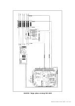
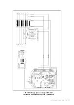
4.2 DER1 connections for typical applications
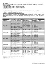
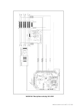
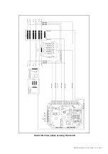
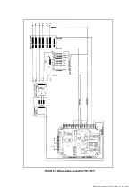
Drawings SCC158, SCC159, SCC160, SCC161 show DER1 regulator connections for typical
applications.
In case of sensing 75V-150V, for example, for ECO/ECP28 – ECO/ECP38 Series alternators with 12
terminals with half-phase reference (and also ECO40-1S, ECO40-2S, ECO401L and ECO40-2L), the
typical drawing for three-phase connection is SCC 158, while for single phase it is SCC 160.
In case of sensing 150V-300V, for example, for ECO43 and ECO46 Series alternators with 12 terminals
with half-phase reference (and also for ECO40-3S, ECO40-1.5L and ECO40-VL), the typical drawing for
three-phase connection is SCC 159, while for single phase it is SCC 161.
5. Setting up the regulator
Selection of the sensing scale takes place directly according to the connection on the power terminal
board; additional settings can be made with 4 trimmers (VOLT, STAB, AMP and Hz) and 3 jumpers
(50/60Hz, JP1 and JP2); the output voltage can also be set with an external analogical signal; additional
settings, including the previous ones but excluding jumpers JP1 and JP2, can be made by modifying the
23 parameters stored in a non volatile integrated memory.
5.1 Alternator voltage signals
Terminals 4-22 of connector CN1 are used for voltage sensing.
5.2 Calibrating sensing
A supplementary calibration may be necessary to compensate any existing tolerances on analogical
voltage acquisition channels; in this case follow the procedure illustrated below.
1. Write
16384
on parameter P[19]
2. Disable VOLT trimmer (from the
Configuration
Menu)
3. Disable Vext (from the
Configuration
Menu)
4. The parameter present in parameter P[5](if three phase sensing) or p[6] (if single phase sensing)has to
be calibrated. Calibration should be adjust in order to obtain 225V from the generator output when the
sensing is cabled to U
FB
(9-10-11-12) and U
FG
(6-7), or to 125.5V if connected U
FB
(9-10-11-12) and
U
HG
(6-7).Please note that a paramenter increment will result in a voltage reduction of the system. It is
recommended to measure the voltage output with an instrument capable to catch the average value of
the voltage.
5. This procedure is necessary to calibrate the voltage sensing of the regulator. The voltage indicated in
location L[36] of the status (It is possible to read it with the DSR terminal software), should match the
value read by the voltage measurement instrument used to calibrate the board on point 4. If a mismatch
is noticed, please proceed in adjusting the P[7] value in order to clear the offset between the indicated
and measured values.
6. Enable the VOLT trimmer again, if it is desired to have it active (from the
Configuration
menu).
7. Enable Vext (from the
Configuration
Menu) if you want to be active.
6. 50/60 Signal
A jumper is located on the 50/60 input (terminals 25 and 26); if enabled from the
Configuration
Menu, it
provokes the commutation of the underspeed protection threshold from 50·(100%-
Hz%) to 60·(100%-
Hz%), where
Hz% represents the position relative to the Hz trimmer or the percentage value entered in
location L[21] (where 10% corresponds to 16384).
7. APO Contact
The acronym
APO
stands for
A
ctive
P
rotection
O
utput: terminals 23 (common) and 24 (collector) 30V-
100mA non-insulated open collector transistor, normally opened, is closed (with a delay that can be
programmed from 1 to 15 seconds) when, among all the alarms, one or more of the active ones can be
selected separately.
Summary of Contents for DER1
Page 10: ...DER1 digital regulator instruction manual rev 03 pag 10 SCC0158 Three phase sensing 75V 150V...
Page 11: ...DER1 digital regulator instruction manual rev 03 pag 11 SCC0159 Three phase sensing 150V 300V...
Page 12: ...DER1 digital regulator instruction manual rev 03 pag 12 SCC0160 Single phase sensing 75V 150V...
Page 13: ...DER1 digital regulator instruction manual rev 03 pag 13 SCC0161 Single phase sensing 150V 300V...
Page 14: ...DER1 digital regulator instruction manual rev 03 pag 14 SCC0202 Single phase sensing 300V 600V...


