DER1 digital regulator instruction manual - rev. 03 - pag. 31
2. Powering DI1
The DI1 board must be powered separately :
1) On connector CN1 (terminals 1-2 and 3-4)
(1)
through the same power as the DSR/DER1; for this
purpose, the power terminals on CN1 have been duplicated (Fig. 11)
2) On connector CN1 (terminals 1 and 4)
(1)
through a dedicated source (AC: 40V/15Hz - 270V/72Hz or
DC: 40V - 380V)
3) Alternatively, on connector CN5 (terminals 1 and 2) through a completely isolated source in DC (9 –
14V).
WARNING
: The use of a non-isolated power on connector CN5 may cause communication
problems that damage the DSR/DER1 regulator, the DI1 interface and the connected devices.
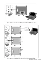
fig. 11:
Example of power and connection (optional) of APO signal
(1) Power supply protected by 500mA fast acting fuse
Summary of Contents for DER1
Page 10: ...DER1 digital regulator instruction manual rev 03 pag 10 SCC0158 Three phase sensing 75V 150V...
Page 11: ...DER1 digital regulator instruction manual rev 03 pag 11 SCC0159 Three phase sensing 150V 300V...
Page 12: ...DER1 digital regulator instruction manual rev 03 pag 12 SCC0160 Single phase sensing 75V 150V...
Page 13: ...DER1 digital regulator instruction manual rev 03 pag 13 SCC0161 Single phase sensing 150V 300V...
Page 14: ...DER1 digital regulator instruction manual rev 03 pag 14 SCC0202 Single phase sensing 300V 600V...


