DER1 digital regulator instruction manual - rev. 03 - pag. 18
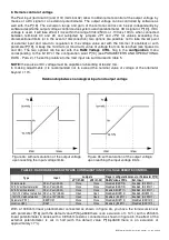
TABLE 6 : EEPROM SETTING REGISTRIES
--'
Description of Parameter
Range
.%
/% /%0
0 Firmware revision
)++6+
13
13
Reserved - Do not write
1 ModBus slave address
6
1
1
Identification of RS485 network (or broadcast)
2 Software configuration
)++6+
16402 18962 Reserved - Do not write
3 Serial number, high part
8
0
0
Reserved - Do not write
4 Serial number, low part
8
0
0
Reserved - Do not write
5
$ 8
)699
16384 16384 Calibration of voltage channels in 3 ph adjustment
6
, 8
)699
16384 16384 Calibration of voltage channels in 1 ph adjustment
7 Measured voltage calibration
)699
16384 16384 Calibration of location L 36 (first “STATUS” box)
8 Current limit time
)699
0
0
Duration of limiting in number of periods
9 Current limit level
)699
32767 32767 Excitation voltage limit upon start-up
10 Word configuration
8
7956
7956 Set from “Configuration” Menu”, see Tab. 7
11
?4@$
)
4
5
n=0…6 is equivalent to a multiplication by 2
n
12
?4@$
)
3
1
namely 1, 2, 4, 8, 16, 32, 64.
13 Coefficient tieing Ki to Kp
)699
16384 26624 Coefficient to set Ki and Kp separately
14 Vout / Vaux Ratio
1699
6000
6000
? A#
15
A !-
)699
16384 16384
! !- ?=5>8
16
? !- !
)699
4608
4608
? - )'B)C699'B)D
17
,<#E
)++6+
126
126
,< #
18 Step limitation reference
)))
20
20
@
0 8
19 Vout Reference
)699
0
0
! !<?$ 8
20 Stability
)699
16384 16384
! $/ 8
21
@A
±
)DA
)699
16384 16384
! FG 8
22
4-
)699
16384 16384
! , 8
23
!2@
)699
9000
9000
!2@
24
!2@
)699
6000
6000
H#
25
)++
20
20
< " -
)I++=):-$<,>
26
<
1699
0
0
!
±
)D "
++2FG
27 Shutdown threeshold
)699
6553
6553 Reserved - Do not write
28
.'-
)699
12287 12287
( -
29
.'-
)699
24575 24575 in the event of AMP alarm
30
$
)++6+
63600 63600
H8#,
31 Reserved
)++6+
-
-
Do not write
/
2. Configuration word (Parameter P[10])
Configuration of the regulator takes place by setting the individual bits of parameter P[10]. Each of them
enables or disables at least one function, on the basis of the fact that its value is respectively 1 or 0.
If the "DSR Terminal" programme is used (see the Chapter on "Use of DSR Terminal monitoring and
programming software"), the setting is facilitated with the
Configuration
menu, where each box enables or
disables a function and corresponds to the respective bit.
Alternatively, the DER1 can be configured by directly setting the value of the P[10] parameter; in this case
the value is calculated before entry, summing the numbers indicated in the column "Value" of Table 7,
corresponding to the functions it is desired t enable.
For example, the default configuration calls for the bits B2, B4 and those from B8 to B12 to be enabled.
The corresponding value is therefore: P[10]=4+16+256+512+1024+2048+4096=7956.
Summary of Contents for DER1
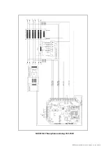
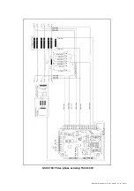
Page 10: ...DER1 digital regulator instruction manual rev 03 pag 10 SCC0158 Three phase sensing 75V 150V...
Page 11: ...DER1 digital regulator instruction manual rev 03 pag 11 SCC0159 Three phase sensing 150V 300V...
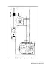
Page 12: ...DER1 digital regulator instruction manual rev 03 pag 12 SCC0160 Single phase sensing 75V 150V...
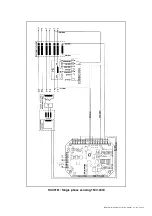
Page 13: ...DER1 digital regulator instruction manual rev 03 pag 13 SCC0161 Single phase sensing 150V 300V...
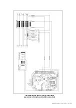
Page 14: ...DER1 digital regulator instruction manual rev 03 pag 14 SCC0202 Single phase sensing 300V 600V...

