DER1 digital regulator instruction manual - rev. 03 - pag. 34
USE OF PROGRAMMING AND MONITORING SOFTWARE DSR TERMINAL
1. Installation
Run the “install.exe” programme from Windows
This creates the directory
C:\dsrterm
, with the executable code, and creates the link on the desktop.
Launch the DSR Terminal program from the Windows desktop.
In case of lack
of shortcut dsr_terminal.lnk on the desktop, it can be copied from
C:\dsrterm
2. Introduction
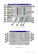
Upon opening the user interface, the program is presented as indicated in the left part of figure 14.
The connection is confirmed when the indicator
Connected
(16) goes from yellow to green.
If the communication takes place without errors, the
Com STAT
indicator (15) goes from red to green.
IMPORTANT:
The communication may take place only if all three of the indicators
Connected
(16)
Com
STAT
(15)
and Com ERROR
(14)
are green. The
ADDRESS
window indicates the slave address with
which it is communicating, almost in real time.
Communication
The
ComPort
menu has 2 functions:
1. Connect/Disconnect
activates or deactivates the connection with the slave unit (DSR/DER1
regulator)
2. Settings
opens a window (as shown in figure 11), through which several parameters, concerning
communications, can be set:
•
The
Port
setting determines which serial port it is intended to use for communications (COM1 or
COM2).
•
The parameter
Slave ADDR
refers to the device with which it is intended to communicate (location L
[1] ).
•
The parameter
Baud
sets the transmission speed with which the master unit (system supervisor)
exchanges data with one or more slave units (digital regulators).
fig. 14
Summary of Contents for DER1
Page 10: ...DER1 digital regulator instruction manual rev 03 pag 10 SCC0158 Three phase sensing 75V 150V...
Page 11: ...DER1 digital regulator instruction manual rev 03 pag 11 SCC0159 Three phase sensing 150V 300V...
Page 12: ...DER1 digital regulator instruction manual rev 03 pag 12 SCC0160 Single phase sensing 75V 150V...
Page 13: ...DER1 digital regulator instruction manual rev 03 pag 13 SCC0161 Single phase sensing 150V 300V...
Page 14: ...DER1 digital regulator instruction manual rev 03 pag 14 SCC0202 Single phase sensing 300V 600V...


