DER1 digital regulator instruction manual - rev. 03 - pag. 29
3. APO output
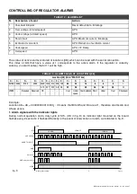
The APO output (Active Protection Output-open collector transistor - terminals 23 and 24 is normally open
during normal operation. It closes (with a programmable delay between 0 to 15 seconds) when, among all
the alarms, one or more than one, separately selectable, is active.
The selection of which alarms involve the activation of the APO depends on the value entered at
parameter P[17].
The transistor is also open when no alarm is activated and with the alarm active, the corresponding
enabling bit is set on 0.
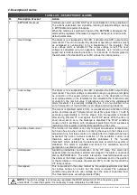
The value to set at parameter P[17] is made up of two parts: one allows selection of the alarms that
activate the contact, while the other permits setting of the delay for intervention. Use the following
procedure to calculate the value to set at parameter P[17]:
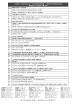
a) With reference to table 15 add up the decimal numbers corresponding to the alarms for which the
APO must be activated, obtaining a number, “B”. (Example: since it is desired to activate the APO in
the case of over voltage and overspeed, the formula is B = 2 + 64 = 66)
b) Multiply the delay it is desired to set (whole numbers from 0 to 15 seconds) for the fixed value of
4096. The number A= (0..15) * 4096 is obtained. (Example: since a delay of 5 seconds is required,
the formula is obtained A = 5 * 4096 = 20480).
The sum of A + B must be entered at parameter P[17] (in the previous example 20480 + 66 = 20546).
)
5
J
1
3
2
'
'
'
'
'
<
H
<4-
H
<
)J
)
+
+
J
12
1
2
TABLE 15 : ALARM SETTINGS THAT ACT ON THE APO
4. DSR operation time
If the regulator is working correctly (no alarm) A12 will be active and the bit 11 will be High at location L
[38].
When we see one alarm, the A12 is deactivated, bit 11 is reset at location L[38] and operation time is
stored.
The total operation time of the regulator is obtained, after the download of the alarms, by adding all the
times TT (last column of the file .alr).
For the procedure please refers to the function “Download Alarm” at the paragraph “Description of
function” of chapters “USE OF PROGRAMMING AND MONITORING SOFTWARE DSR TERMINAL”.
Summary of Contents for DER1
Page 10: ...DER1 digital regulator instruction manual rev 03 pag 10 SCC0158 Three phase sensing 75V 150V...
Page 11: ...DER1 digital regulator instruction manual rev 03 pag 11 SCC0159 Three phase sensing 150V 300V...
Page 12: ...DER1 digital regulator instruction manual rev 03 pag 12 SCC0160 Single phase sensing 75V 150V...
Page 13: ...DER1 digital regulator instruction manual rev 03 pag 13 SCC0161 Single phase sensing 150V 300V...
Page 14: ...DER1 digital regulator instruction manual rev 03 pag 14 SCC0202 Single phase sensing 300V 600V...

