


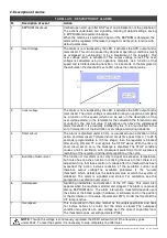


DER1 digital regulator instruction manual - rev. 03 - pag. 19
Bit
Value
Function
/
B0
1 Not used
0
B1
2 Periodical reference variation
0
B2
4 Automatic voltage offset compensation
(1)
1
B3
8 Not used
0
B4
16 Enable hardware jumper 50/60Hz
1
B5
32 Free for future use
0
B6
64 Force three-phase sensing
0
B7
128 External location reference L[49]
(2)
and activation of saturation in the event of overflow
0
B8
256 Enable VOLT TRIMMER
1
B9
512 Enable STAB TRIMMER
1
B10
1024 Enable Hz TRIMMER
1
B11
2048 Enable AMP TRIMMER
1
B12
4096 Enable external analogical input
1
B13
8192 Enable external DAC
0
B14 16384 60 Hz setting in the event of disabling of the 50/50 Hz hardware jumper
0
B15 32768 Reserved
0
TABLE 7 : BIT FUNCTION OF THE CONFIGURATION WORD (PARAMETER P[10] )
NOTE 1: only with single phase reference
NOTE 2: if analogical input is disabled
NOTE 3: for analogical input
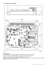
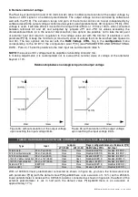
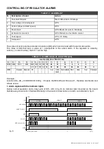
3. RAM location reference, activation of saturation in analogical remote control
The
RAM Voltage CTRL
Flag (corresponding to bit 7 of the P[10] configuration word) performs two
functions:
1. If the Pext hardware input is enabled (Flat Ext. Input corresponding to bit 12 of the P[10] configuration
word), as previously described, the
RAM Voltage CTRL Flag
activates saturation of output voltage
when the analogical control voltage reaches the limit foreseen for input, to which it is applied (see
Para. 8 Remote control of voltage).
If saturation is enabled, in the event of removal of the Vext/Pext connection (due to accidental
opening, for example) the voltage goes to the maximum value set in parameter P[16] (+14% by
default).
2. When Pext is disabled by hardware, the indicated flag defines the value to be used by the software
control of the output voltage. If RAM Voltage CTRL is deactivated (B7=0), the non volatile parameter P
[15] is used (therefore following shut down and restart of the regulator, the last value memorised
remains set): on the start up the location L[49] is initialised with the value of parameter P[15] and is
kept aligned to that value. Editing of location L[49] has no effect in this working condition. If RAM
Voltage CTRL is active (B7=1) the volatile location L[49] is used for software remote control of the
output voltage (when the regulator is energized, the value is stored. If the regulator is shut down, the
value is lost). This function is particularly useful for the applications of alternators in parallel with grid,
when the regulation of the reactive power exchanged is controlled by means of a third party supplied
digital supervisor.
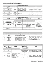
FLAG
RAM
Voltage CTRL
P[10] Bit B7
FLAG
Ext. Input
P[10] Bit B12
Output voltage control type
0
1
Analogical without saturation
1
1
Analogical with saturation
0
0
Digital - Parameter P[15]
1
0
Digital - Location L[49]
TABLE 8 : REMOTE VOLTAGE CONTROL FLAGS FUNCTION
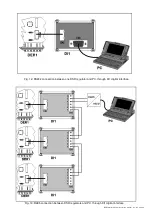
Summary of Contents for DER1
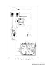
Page 10: ...DER1 digital regulator instruction manual rev 03 pag 10 SCC0158 Three phase sensing 75V 150V...
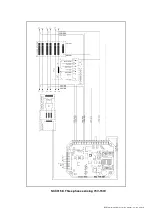
Page 11: ...DER1 digital regulator instruction manual rev 03 pag 11 SCC0159 Three phase sensing 150V 300V...
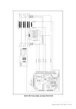
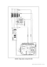
Page 12: ...DER1 digital regulator instruction manual rev 03 pag 12 SCC0160 Single phase sensing 75V 150V...
Page 13: ...DER1 digital regulator instruction manual rev 03 pag 13 SCC0161 Single phase sensing 150V 300V...
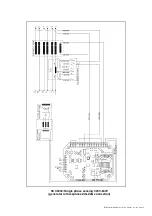
Page 14: ...DER1 digital regulator instruction manual rev 03 pag 14 SCC0202 Single phase sensing 300V 600V...


