


DER1 digital regulator instruction manual - rev. 03 - pag. 28
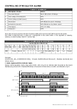
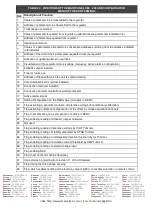
2. Description of alarms
N.
Description of event
Action
1
EEPROM checksum
Verified upon start up (after DSP reset and initialisation of the peripheral).
The actions undertaken are: signalling, locating of default settings, saving
in EPPROM and regulator blockage.
When the machine is switched on again, if the EEPROM is damaged, the
alarm will be repeated. Otherwise the regulator will begin to function with
default parameters.
2
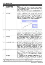
Over Voltage
The alarm is not visualised by the LED, it activates the APO output and is
memorised. This can be caused by abnormal operating conditions (such
as overspeed or overloading) or by a breakdown of the regulator. The
over voltage alarm is activated if the output voltage is lost. The over
voltage is calculated using an opportune template, as a function of the
speed and is inhibited during transition, for 2 seconds. In the template for
the calculation the threshold is set at 5% above the nominal value.
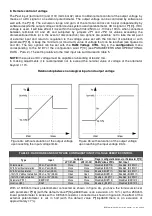
3
The alarm is not visualised by the LED, it activates the APO output and is
memorised. The under voltage is calculated using an opportune template
as a function of the speed (which can be seen in the description of the
over voltage alarm); in the template for the calculation the threshold is set
at under 5% the nominal value. It intervenes only above the underspeed
alarm threshold; it is practically inhibited by this. It is also inhibited in the
ent of intervention of the Excitation over voltage and during transients.
4
Short circuit
The alarm is disabled under 20 Hz, is visualised upon activation of the
action and memorised. Tolerated short circuit time goes from 0,1 to 25,5
seconds (programmable in 100 ms steps); then the regulator is blocked
after saving DD and TT and signals the STOP status. With the time in
short circuit set on zero, the blockage is disabled. The STOP condition
causes a fall in excitation, with consequent switching off and successive
restarting of the regulator and therefore repetition of the cycle.
5
Excitation Overcurrent
The function of this alarm is not only to signal an excessive temperature,
but it also has an active function in reducing the cause. In fact, there is an
adjustment ring that takes control of voltage after the threshold has been
exceeded; the action involves reduction of the excitation current and
therefore output voltage.The available parameter is the "current
threshold", which determines the balanced value at which the system is
stabilised. The alarm is signalled and stored. For calibration see the
paragraph on excitation overcurrent.
6
Underspeed
Signalling (immediate) and activation of the V/F ramp. This alarm also
appears when the machine is started and stopped. The alarm is not saved
among EEPROM data. The alarm intervention threshold depends upon
the status of the 50/60 jumper (hardware or software) and on the position
of the Hz trimmer or the value of parameter P[21]. Under the threshold the
V/F ramp is active.
7
Overspeed
This is visualised in the same manner as the underspeed alarm and does
not involve actions on control, but the alarm is stored. The overspeed
condition may provoke an over voltage as in the case of capacitive load.
The threshold can be set with parameter P[26].
TABELLA 14 : DESCRIPTION OF ALARMS
NOTE
: Though the voltage is continuously regulated, the DER1 will switch off if the frequency goes
under 20Hz. To reset the system it is necessary to stop completely the alternator.
Summary of Contents for DER1
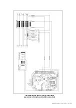
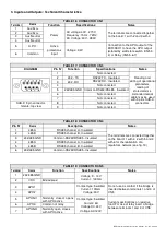
Page 10: ...DER1 digital regulator instruction manual rev 03 pag 10 SCC0158 Three phase sensing 75V 150V...
Page 11: ...DER1 digital regulator instruction manual rev 03 pag 11 SCC0159 Three phase sensing 150V 300V...
Page 12: ...DER1 digital regulator instruction manual rev 03 pag 12 SCC0160 Single phase sensing 75V 150V...
Page 13: ...DER1 digital regulator instruction manual rev 03 pag 13 SCC0161 Single phase sensing 150V 300V...
Page 14: ...DER1 digital regulator instruction manual rev 03 pag 14 SCC0202 Single phase sensing 300V 600V...


