


DER1 digital regulator instruction manual - rev. 03 - pag. 25
4) Slowly turn the “Hz” trimmer, rotating it clockwise until the generator voltage begins to drop and
ascertain that the indicator light simultaneously begins flashing rapidly.
5) By increasing speed, the generator voltage will normalise and the alarm will disappear.
6) Set the speed to the nominal value
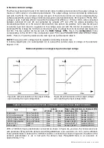
Underspeed and Overspeed protection (P21, P23 & P26)
0,00%
20,00%
40,00%
60,00%
80,00%
100,00%
120,00%
20%
40%
60%
80%
100%
120%
f/fnom
V/Vnom
P21=16384 @ P23=9000
P21=32767 @ P23=9000
P21=0 @ P23=9000
P26=0
P26=32767
P26=-32767
P23=32767
P23=15000
P23=0
fig. 8:
Parameters 21, 23 and 26
5. Overspeed
Parameter P[26]
sets the overspeed alarm intervention threshold; if it is set on 0, the signal cuts in at 55
Hz (if the 50/60 jumper and 50/60 setting in the Configuration Menu are absent) or at 66Hz (if the 50/60
jumper is present and enabled or the 50/60 flag in the Configuration Menu is activated). Values between
65535 (-1) and 32768 (-32767) lower the threshold proportionately to 50 Hz and 60 Hz, respectively;
values between 0 and 32767 raise the threshold proportionately, respectively to 60 Hz and 72 Hz; refer to
the broken lines in figure
8.
6. Other parameters
6.1 Vout / Vaux Ratio
In order to guarantee sufficient feeding voltage at speeds lower than the Hz protection intervention
threshold, a limit to the reduction of voltage has been foreseen, as a function of frequency.
The limit concerns regulated voltage (Vout). Should the DER1 be powered through an auxiliary winding, it
must be born in mind that the voltage generated by the winding (Vaux) may not have the same Vout value;
Vaux is considered proportionate to Vout and the proportional coefficient is determined by
parameter P
[14].
If the DER1 is powered directly by the regulated phase, parameter 14 should be set on 0; in case it is
powered by auxiliary winding or PMG, the voltage (Vaux) must be measured, in no-load conditions and
with output voltage regulated on the nominal value (Vout); the value of parameter P[14] can be obtained
with the following formula:
−
⋅
=
1
32767
]
14
[
Vaux
Vout
P
Summary of Contents for DER1
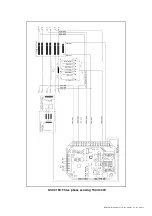
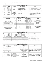
Page 10: ...DER1 digital regulator instruction manual rev 03 pag 10 SCC0158 Three phase sensing 75V 150V...
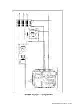
Page 11: ...DER1 digital regulator instruction manual rev 03 pag 11 SCC0159 Three phase sensing 150V 300V...
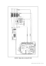
Page 12: ...DER1 digital regulator instruction manual rev 03 pag 12 SCC0160 Single phase sensing 75V 150V...
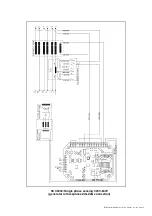
Page 13: ...DER1 digital regulator instruction manual rev 03 pag 13 SCC0161 Single phase sensing 150V 300V...
Page 14: ...DER1 digital regulator instruction manual rev 03 pag 14 SCC0202 Single phase sensing 300V 600V...


