


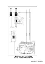


DER1 digital regulator instruction manual - rev. 03 - pag. 17
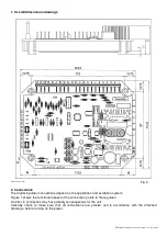
Fig. 4a: 100K external potentiometer connection
Fig. 4b: 25K external potentiometer connection
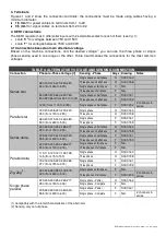
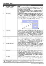
PARAMETERS AND OPERATING DATA
1. ModBus registry list
An EEPROM memory is used to store configuration parameters and other information that must not be lost
when the generator goes off. Parameters can be read/written and machine operational settings entered
through serial connections. Two versions of the regulator are available, called DER1 and DER 1/A; they
differ primarily in the default value of several parameters. Table 6 shows a complete list of the parameters
that can be set, which define all the operational conditions of the regulator.
Note:Locations are ordered to separate the parameters of individual regulators (S.N:, SW versions and
calibration) from settings foreseen, in order to facilitate programming of regulators with the same settings
but different S.N., SW versions and calibrations. The parameters from 0 to 9 are adjusted at the factory for
each regulator. The parameters from 10 to 30 can therefore be freely copied from one to another.
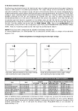
9. VOLT, STAB, Hz and AMP Trimmers
The trimmers are enabled by the software from the
Configuration
Menu; if they are not enabled, they
DO
NOT
perform any function.
The
VOLT
trimmer allows adjustment from about 75V to about 150V or from about 150V to about 300V.
The
STAB
trimmer adjusts the dynamic response (statism) of the alternator under transient conditions.
The
Hz
trimmer allows for a variation of the "low speed protection" of up to –20% with respect to the
nominal speed value set by the 50/60 jumper (if activated) or by the 50/50 box in the
Configuration
menu
(at 50 Hz the threshold can be calibrated from 40 Hz to 50 Hz, at 60 Hz the threshold can be calibrated
from 48 Hz to 60 Hz).
The
AMP
trimmer adjusts the excitation overcurrent protection intervention threshold.
10.Serial Communications
The COM connector is RESERVED for connection to the Dl1 communications module with the special
cable provided with the module itself.
The serial interface of the Dl1 communications unit is of the RS232 or RS485 type: it will therefore be
possible to connect several DER1-Dl1 groups as well (and therefore several generators) in parallel on the
same 485 Bus, in order to monitor the operation with a single supervising unit. The regulator implements a
subsystem of the MODBUS standard for communications; the DI1-DER1 set performs slave operation,
whose address is memorised in the EEPROM and is set during the phase of configuration.
When necessary, the DI1
interface permits insertion of the regulator in a RS485 network with other
regulators or other devices of a different type, but with the same type of bus. Contact the Mecc Alte
technical office for detailed descriptions of the ModBus commands implemented.
The “Master Unit” is made up of a PC or other dedicated equipment and can access the parameters and
functions of the regulator.
The master unit has the following possible functions:
•
Repetition, or visualisation, of the generator status variables, even from a remote location
•
Setting of single parameters
•
Uploading and downloading of settings files
•
Status readings (alarms, measuring variables)
•
Readings of the alarm memory information
Summary of Contents for DER1
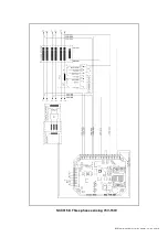
Page 10: ...DER1 digital regulator instruction manual rev 03 pag 10 SCC0158 Three phase sensing 75V 150V...
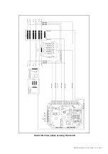
Page 11: ...DER1 digital regulator instruction manual rev 03 pag 11 SCC0159 Three phase sensing 150V 300V...
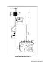
Page 12: ...DER1 digital regulator instruction manual rev 03 pag 12 SCC0160 Single phase sensing 75V 150V...
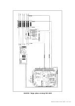
Page 13: ...DER1 digital regulator instruction manual rev 03 pag 13 SCC0161 Single phase sensing 150V 300V...
Page 14: ...DER1 digital regulator instruction manual rev 03 pag 14 SCC0202 Single phase sensing 300V 600V...


