DER1 digital regulator instruction manual - rev. 03 - pag. 2
INDEX
pag. 2
INTRODUCTION
pag. 3
MAIN CHARACTERISTICS
pag. 3
1.
Architecture of the system
pag. 3
1.1 Regulator
pag. 3
1.2 Communications module
pag. 3
2.
Technical Characteristics
pag. 4
3.
Inputs and Outputs: technical specifications
pag. 5
4.
Block diagram
pag. 6
INSTALLATION
pag. 6
1.
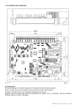
Overall dimensions drawings
pag. 7
2.
Connections
pag. 7
3.
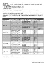
Terminals
pag. 8
4.
DER1 connections
pag. 8
4.1 Connections based on voltage
pag. 8
4.2 DER1 connections for typical applications
pag. 9
5.
Setting up the regulator
pag. 9
5.1 Alternator voltage signals
pag. 9
5.2 Calibrating sensing
pag. 9
6.
50/60 Signal
pag. 9
7.
APO Contact
pag. 9
8.
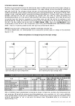
Remote control of voltage
pag. 14
9.
VOLT, STAB,Hz and AMP Trimmers
pag. 15
10.
Serial communications
pag. 15
PARAMETERS AND OPERATING DATA
pag. 15
1.
ModBus registry list
pag. 15
2.
Word of configuration (Parameter P[10])
pag. 16
3.
pag. 17
Volatile memory addresses
pag. 18
5.
Fourth Status Word (Location L[39])
pag. 18
SETTING OF VOLT, STAB, AMP and Hz PARAMETERS
pag. 19
1.
Voltage
pag. 19
1.1
Setting voltage
pag. 19
1.2 Soft Start
pag. 19
1.3
Slow voltage variations
pag. 20
2.
Stability
pag. 20
2.1
Adjustment of stability
pag. 20
3.
Excitation overcurrent
pag. 20
3.1 Description
pag. 20
3.2 Calibration with a supervision unit
pag. 21
3.3 Calibration without a supervision unit
pag. 21
4.
Underspeed
pag. 22
4.1 Description
pag. 22
4.2 Calibration with a supervision unit
pag. 22
4.3 Calibration without a supervision unit
pag. 22
5.
Underspeed
pag. 23
6.
Other parameters
pag. 23
6.1
Vout / Vaux Ratio
pag. 23
6.2
V/F slope at start up
pag. 24
6.3
Short cirrcuit time
pag. 24
CONTROLLING OF REGULATOR ALARMS
pag. 25
1.
Alarm signals with the indicator lights
pag. 25
2.
Description of alarms
pag. 26
3.
APO Output
pag. 27
4.
Board operation time
pag. 27
DI1 COMMUNICATIONS UNIT
pag. 28
1.
Description
pag. 28
2.
Powering DI1
pag. 29
3.
Inputs and Outputs: technical specifications
pag. 30
USE OF PROGRAMMING SOFT. AND MONITORING OF THE DSR TERMINAL
p
ag. 32
1.
Installation
pag. 32
2.
Introduction
pag. 32
3.
Description of function
pag. 33
4.
Setting Files
pag. 34
Summary of Contents for DER1
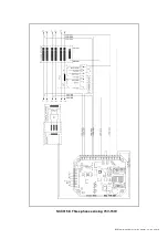
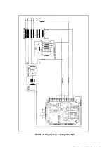
Page 10: ...DER1 digital regulator instruction manual rev 03 pag 10 SCC0158 Three phase sensing 75V 150V...
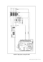
Page 11: ...DER1 digital regulator instruction manual rev 03 pag 11 SCC0159 Three phase sensing 150V 300V...
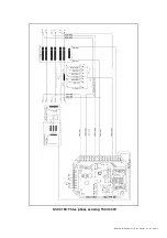
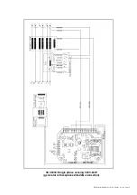
Page 12: ...DER1 digital regulator instruction manual rev 03 pag 12 SCC0160 Single phase sensing 75V 150V...
Page 13: ...DER1 digital regulator instruction manual rev 03 pag 13 SCC0161 Single phase sensing 150V 300V...
Page 14: ...DER1 digital regulator instruction manual rev 03 pag 14 SCC0202 Single phase sensing 300V 600V...

