


Part Number 020002365 08/25/2015 9
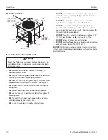
General
• Refrigeration units require stand or 6" (15.2 cm) legs.
Refrigeration unit cannot be placed directly on floor.
• Conduit can be run through floor or ceiling chase.
• Syrup supply can be located on stand or adjacent to
refrigeration unit.
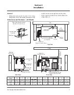
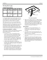
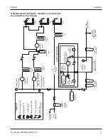
Dimensions and Clearances — All Models
W
all
6" (15.2 cm)
Diameter Chase minimum
3-7/8" (9.8 cm) Diameter
(4-7/8" [12.4 cm] Diameter
on Model 50)
Air Flow
Control
Switches
18"
(45.7 cm)
minimum
J
Electrical
Junction Box
6" (15.2 cm) minimum
12"
(30.5 cm)
minimum
W
all
Wall
Top View
Front View
Side View
P
W
all
Electrical
Junction Box
Incoming Water
Line
Incoming CO
2
Supply Line
Incoming Syrup
Supply Lines
Drain Connection
W
Ceiling
W
all
18" (45.7 cm)
minimum
I
H
CO
2
Regulator
Panel (Optional)
N
Drain Connection
Floor drain should be located
within 6 ft (183 cm) of unit
W
all
Conduit to
Dispensing Towers
D
Water Condenser Connections
(Models 42, 44 and 50 only)
K
Incoming Water
Connection
Drain Connection
L
M
Model
W
D
H
I
(with stand)
J
K
L
M
N
P
42, 44 &
SC1000
39-3/4"
(101 cm)
24-3/4"
(62.9 cm)
28-1/4"
(72.4 cm)
60-3/4"
(154.3 cm)
11"
(28 cm)
3-1/2"
(8.9 cm)
12"
(30.5 cm)
4"
(10.2 cm)
6"
(15.2 cm)
12"
(30.5 cm)
50 &
SC2000
42-1/4"
(107.3 cm)
28-1/4"
(71.8 cm)
32-1/4"
(81.9 cm)
66-3/4"
(169.5 cm)
11"
(28 cm)
4"
(10.2 cm)
19"
(48.2 cm)
19"
(48.2 cm)
8-1/2"
(21.6 cm)
14"
(35.6 cm)
Section 2
Installation


