background image

Special methods 

32 


NANOCOLOR

®


UV

/

VIS

 II and 

NANOCOLOR

®


VIS

 II   V 1.1 / 10.2017 

1100 nm


range (

NANOCOLOR

®


UV

/

VIS

 II) or 320 nm - 1100 nm range (

NANOCOLOR

®


VIS

 II) 

can be entered.  


Zero link:

 When the "Barcode link" option is used, the "Zero link" option is enabled. When the 

corresponding test is selected, the zero stored for the MACHEREY-NAGEL tube test will be 
used  for  the  calculation.  This  allows  a  measurement  without  a  zero  solution.  This  option  is 
available only for the test which was selected in the context of the barcode link and for which 
a zero is already stored in the photometer.  


Cuvette size:

 Select the cuvette size from the displayed list box. When methods are carried 

out, the photometer detects automatically whether the correct cuvette is being used.  


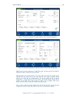
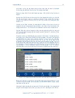
Formula:

 The formula field is where the factors for the final calculation of the measurement 

result  are  entered.  Formulas  to  the  4th  degree  can  be  entered.  Tapping  on  the  individual 
fields  will  open  a  numeric  keypad  for  entering  numerical  values

.

  Negative  factors  can  be 

depicted by entering a minus sign before the numeric value. 


Please note: The formula has the format y = F0 + F1*E + F2*E

2

 + F3*E

3

 + F4*E

4

 with E as 

absorbance value and F as factors of the equation. The factors are input as an equation, as 
determined by a plot of concentration values (x-axis) against the absorbance values (y-axis).  


After successfully entering all parameters, confirm the entries with 

 . The method will be 

saved and included in the list of user methods (see section 5.4.2.1). The properties that were 

entered can be edited there via the 

 icon. A report on the special method properties and 

data  can  be  printed  by  pressing  the 

  icon  and  selecting  "Print."  The  entries  "Export  to 

PNG  file"  and  "Export  to  CSV  file"  allow  the  method  report  to  be  exported  to  a  connected 
storage medium.  

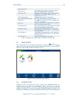
5.4.2.3 

Calibration 

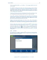
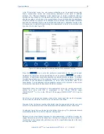
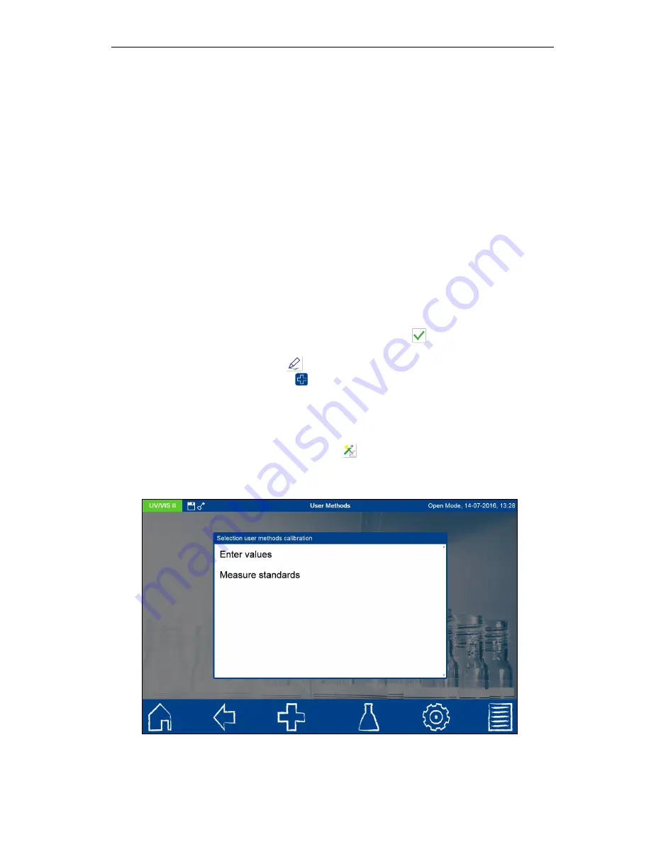
The  Calibration menu  is opened  by  pressing  the 

  icon.  This  menu is  used  to  determine 

absorbance values for standard solutions of known concentrations as part of creating a user-
defined special method (see Figure 34).  


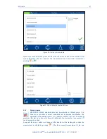
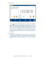
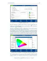
Figure 34: Selection of the mode for calibrating a special method  


Summary of Contents for NANOCOLOR UV/VIS II

Page 1: ......

Page 2: ...iew 10 3 2 Back view 11 4 Operating instruction 11 4 1 Connectivity 11 4 2 Turning on the instrument 11 4 3 Operation and user guidance 12 4 3 1 Operation of the touch screen 12 4 3 2 Task and status...

Page 3: ...5 Yellowness Index 49 5 6 6 6 Hazen APHA PtCo color index 49 5 6 7 Visual color scales 50 5 6 7 1 Iodine color index 50 5 6 7 2 Ph Eur color index 50 5 6 8 Distinction of the color index according to...

Page 4: ...additions 80 6 6 6 IQC counter 82 6 6 7 IQC memory 82 6 6 8 IQC Card 4 84 6 7 User accounts 86 6 8 Pictograms 88 6 9 Data export 89 6 9 1 LIMS 89 6 9 2 ACRON 90 6 10 Tools 90 6 10 1 Timer 91 6 10 2 L...

Page 5: ...Content iv NANOCOLOR UV VIS II and NANOCOLOR VIS II V 1 1 10 2017 10 3 Spare parts accessories and consumables 98 10 4 Contact 99 10 5 Warranty liability and complaints 99 10 6 Waste disposal 99...

Page 6: ...armonization legislation of the European Community listed below European Directive 2011 65 EU on the restriction of the use of certain hazardous substances in electrical and electronic equipment RoHS...

Page 7: ...em Monochromator Wavelength range 190 nm 1100 nm 320 nm 1100 nm Wavelength accuracy 1 nm Wavelength resolution 0 1 nm Wavelength calibration Automatic Wavelength selection Automatic barcode manual Sca...

Page 8: ...king with chemicals can be hazardous Handling chemicals without protection can lead to serious injuries When working with the NANOCOLOR spectrophotometers wear the required personal protective equipme...

Page 9: ...terium lamp generates ultraviolet radiation which can harm your eyes Never look directly into the light source without suitable UV protection glasses Also protect your skin against direct UV light The...

Page 10: ...slot cover Protective covering Power plug only for NANOCOLOR UV VIS II Power supply with country specific adapters only for NANOCOLOR VIS II USB connection cable Quickstart guide Calibration cuvette M...

Page 11: ...break nor other damages Otherwise there is an imminent danger of an electric shock 4 1 Connectivity Next to the electrical connection four more types of interfaces are available within the NANOCOLOR U...

Page 12: ...capacitive touch screen PCAP The instrument s cover glass is non reflecting It can be easily and conveniently cleaned with the microfiber cloth included in your package or with a soft cotton cloth Fi...

Page 13: ...numbers or special characters Figure 10 Text keypad II Pressing the key on the special character layout will switch to another keypad of special characters Via the text keypad this key is used to capi...

Page 14: ...ease consider that some menus cannot be retrieved by pressing the icon e g measurement menu as the process has been ended by leaving the respective menu Feature icon By tapping this icon one can activ...

Page 15: ...ng a checkbox with a checkmark deactivates the box and removes the checkmark 4 3 5 List functions When editing text or numeric fields it is possible that a selection window with a list will be opened...

Page 16: ...firming with opens the measurement window Inserting the zero solution and pressing will initiate the zero measurement After the successful measurement of the zero solution the sample solution needs to...

Page 17: ...figure 18 Figure 18 Result window of the absorbance measurement The absorbance of the individual wavelengths can be displayed by selecting the appropriate wavelength from the list on the left Use the...

Page 18: ...zero measurement After the successful measurement of the zero solution the sample solution needs to be inserted Pressing starts the measurement process After the measurement has been completed the me...

Page 19: ...con from the sample information bar the procedure is similar This time the icon must be removed from the blue flashing sample information bar with a wiping motion after holding it down The following s...

Page 20: ...s still within the measuring range but outside of the 20 80 measuring range If the bar is colored red the measured value is out of range The Correction measurement option can be used when a correction...

Page 21: ...t box 5 2 2 Standard tests MACHEREY NAGEL standard tests can be selected in different ways It is however not possible to select a standard test by barcode identification The appropriate measurement me...

Page 22: ...ys requires determination of a correction value Color and turbidity both cause increased light absorption increased absorbance which leads to wrong results Determination of correction values requires...

Page 23: ...0 Almost all colors and turbidities are destroyed under test conditions and do not interfere COD resistant colors and turbidities cause deviating results which cannot be circumvented 0 31 Cyanide 08 P...

Page 24: ...ube add 4 0 mL sample solution close mix 0 70 POC 200 Proceed as described in the instructions for test 0 70 but instead of 1 0 mL R2 add 1 0 mL distilled water 0 71 Nickel 4 Proceed as described in t...

Page 25: ...lution consider dilution mix add 2 drops R3 close and mix 8 59 Methanol 15 Open methanol test tube add 3 0 mL R1 and 1 5 mL sample solution consider dilution mix add 2 drops R3 close and mix 8 71 Pero...

Page 26: ...s MEBAK 2 23 Thiobarbituric acid value MEBAK 2 4 acids MEBAK 2 18 2 Iso acids MEBAK 2 18 2 Cyclamate MEBAK 3 11 4 Iron MEBAK 2 29 3 Free amino nitrogen FAN MEBAK 2 8 4 1 Total carotenoids acc to Weser...

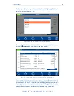
Page 27: ...Figure 26 Options for user method creation 5 4 2 1 Lists Pressing the icon opens the list containing all of the special methods that have already been created by the user Besides the scroll function...

Page 28: ...er pressing the icon a list box will open showing the methods on the mass storage device available for import see Figure 28 Tapping on the desired entry will import the special method into the list of...

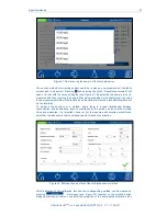
Page 29: ...m the list and confirm with 5 4 2 2 Design The design menu allows you to create special methods based on previously established method information such as factors and wavelengths of the measurement In...

Page 30: ...specific number with which the method can be retrieved later from the list box in the User methods menu Enter a method number between 1 and 99 using the numeric keypad The lowest available number wil...

Page 31: ...le Calculation formula multi wavelength measurements In this section the wavelengths and coefficients given in the selected calculation formula are defined The number of wavelengths is determined by t...

Page 32: ...en a numeric keypad for entering numerical values Negative factors can be depicted by entering a minus sign before the numeric value Please note The formula has the format y F0 F1 E F2 E2 F3 E3 F4 E4...

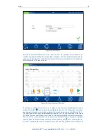
Page 33: ...he statistical certainty level of the calibration function a multiple determination can also be performed for the respective concentrations To do so enter the desired value of the concentration The ab...

Page 34: ...1 E2 as absorbance value of wavelength 2 K1 as a multiplication factor of the wavelength 1 K2 as a multiplication factor of the wavelength 2 etc To include a subtraction step in one of the formulas th...

Page 35: ...to the graph and can be included or excluded by selecting or deselecting the checkbox in front of the pair of values in the analysis Following the deselection or selection of data pairs the calibrati...

Page 36: ...ng and tapping the entry Statistical data see Figure 40 Figure 40 View of the statistical data of the user defined special method When creating calibration curves outliers can occur due to errors in t...

Page 37: ...laced and the calibration function and statistical data will be re calculated To increase the accuracy of a method where there is a linear relationship between concentration and absorbance each concen...

Page 38: ...e entry Print In the case of special methods based on a calibration as described in Section 5 4 2 3 the measured absorbance and concentration pairs can be viewed and edited via the entry Edit calibrat...

Page 39: ...be entered using the icons located below the result window Press the icon to view other available options Via the Properties command new sample information can be added below the measurement menu see...

Page 40: ...ne can decide via option buttons to perform either a color measurement or a color comparison against a reference as far as a color reference is defined via the color analysis menu already yet figure 4...

Page 41: ...assigned with a serial number To analyze the color measurement use the Analysis command or select the result from the memory and press Pressing the Do not save command prevents the measurement result...

Page 42: ...hree dimensional coordinate system containing all colors that the human eye can perceive Every color clearly corresponds to a point in the coordinate system The position of a color in the color space...

Page 43: ...e the color of a batch with the color of a product specification the procedure of color comparison described in this section can be used The color references function was conceived for these kinds of...

Page 44: ...e list in the middle of the color analysis menu as well as a color reference from the list of color references must be choosen The calculated result is expressed in the result view as a DE value Figur...

Page 45: ...e shows the result of the measurement in the result view screen figure XX The device automatically evaluates the measurement The measured DE value is compared against the accepted DE value of the colo...

Page 46: ...nalysis mode in the color analysis menu Mark the color measurements which are supposed to be compared The device automatically calculated a maximal DE value which is display in the result view Figure...

Page 47: ...gar color beer color according to EBC and ASBC yellowness index Hess Ives color unit coloring according to Ph Eur Gardner color index ADMI color index ASTM color index Saybolt color index Klett color...

Page 48: ...ightest value to 18 darkest value and is measured in 10 mm cuvettes The Gardner color indexes are defined by the CIE chromaticity coordinates x and y All of the color indexes are defined by a calibrat...

Page 49: ...mg L Pt but it could also be colored red green or blue The ADMI values are not obtained by comparison with the PtCo calibration but rather calculated based on the standard AWWA 2120F through a 4th deg...

Page 50: ...color standards for red cobalt chloride HCl blue copper chloride HCl and yellow iron III chloride HCl These are used to mix five color schemes for the colors red brown brown yellow yellow and yellow g...

Page 51: ...urement value over a range of about 50 nm Klett photometers are still used today in bioanalysis for monitoring the growth of cell cultures However it is not the absorption that is measured but rather...

Page 52: ...asuring takes longer than with other colorimeters A color measurement ZERO or sample takes about 30 seconds at an integration from 360 nm to 830 nm 5 6 13 Combinations of illuminants observers and cuv...

Page 53: ...able 3 Allowable combinations of illuminants observers and cuvette types 5 7 Test number Besides opening the measurement menu of the cuvette tests via barcode detection it can also be opened by select...

Page 54: ...nu Press the icon to open the main menu Now you can choose from the options shown in Figure 59 Figure 59 Main menu 6 1 Settings In this menu general settings for the instrument can be made or options...

Page 55: ...applied Changing the regional settings will affect the display of the measurement result This can change the way the thousands separator and the decimal place are depicted Example DE Germany 1 567 22...

Page 56: ...the date and time display can be seen in the lower left hand corner of the pop up window Figure 63 Setting the date and time 6 1 4 Memory settings Press the icon to view the memory settings Besides an...

Page 57: ...ent results memory is only available in the Open Mode see also Section 6 6 2 The setting will be saved upon exiting the menu 6 1 5 Acoustic signal Press the icon to adjust and test the sound level of...

Page 58: ...contain all information about a measurement In case the checkbox is not set the measurement results on the printout will only contain the most important information Setting the checkbox Inverted print...

Page 59: ...Figure 68 will activate the function and a reaction time flag will appear in the status bar The setting will be saved upon exiting the menu Figure 68 Acivate Reaction time 6 1 9 Lamp control Press th...

Page 60: ...ansmission in tube tests The result of the turbidity measurement is stored together with the actual measurement result Press the icon to open a window for turning on this function Mark the checkbox to...

Page 61: ...be applied To connect the sipper pump to the spectrophotometer please consult Section 6 5 1 and observe the instructions in the sipper manual The settings will be saved upon exiting the menu Figure 71...

Page 62: ...r to continue the process Confirming with OK opens a list of backup files available on the internal SDHC card The file names are marked with the date and time Select a backup file in order to import i...

Page 63: ...ou set the time for the display to switch off when not in use in order to save energy Simply tap on the black display in the energy saving mode to switch it back on and start using the instrument The...

Page 64: ...re version and the number of system starts are listed Please have this information ready when contacting the MACHEREY NAGEL technical support Figure 76 System info 6 2 2 System check Press the icon to...

Page 65: ...icons and select the required update file from the list Wait until a message appears indicating the termination of the update process This process can take up to a few minutes Restart your device whe...

Page 66: ...ibration will continue automatically When calibration is complete the date of calibration is stored in the device and displayed the next time the calibration process is activated 6 4 2 Turbidity calib...

Page 67: ...tings In the connectivity settings see Figure 81 the various types of interfaces on the device can be controlled It is not possible to send several records at the same time through an interface The as...

Page 68: ...roblems make sure the connectivity settings match the connected devices see Section 6 9 1 Figure 82 RS232 settings 6 5 3 LAN Press the icon to open the overview of the LAN settings Figure 83 If the de...

Page 69: ...es and spike additions that are stored in the menu are based on German requirements they can always be changed by the user Figure 84 IQC Menue 6 6 1 Monitoring of inspection measuring and test equipme...

Page 70: ...igure 86 Please note This selection is omitted in the user guide of the NANOCOLOR VIS II The halogen lamp is checked directly Figure 86 Selection of lamps in the lamp check menu After selecting the la...

Page 71: ...onding value entered via the alphanumeric keypad The data for the input NANOCHECK lot will be saved automatically after the program is run for the first time Alternatively a pre programmed LOT can be...

Page 72: ...ues are within the specified confidence intervals the test will be given a Passed rating Figure 89 Results of the screening using the NANOCONTROL NANOCHECK Via the icon the result of the test can be p...

Page 73: ...m with potassium nitrate there is an alternative stray light test available for to the UV range at 220 nm using potassium iodide To perform a stray light test you need the appropriate solutions and a...

Page 74: ...so www mn net com Press the icon to open the window for specifying the desired standards see Figure 94 Select the entry Standard to open the list of pre defined standards in the device Now either the...

Page 75: ...ving the cuvette or exiting the measurement menu by means of one of the other icons in the task bar will end the measurement process and save the result in the IQC memory see Section 6 6 7 of the devi...

Page 76: ...list for standard selection along with the test number and test name see Figure 94 User defined Standard entry Figure 95 Creating a user defined standard Tap the entry Method and then select the meth...

Page 77: ...d of the multiple determination see Figure 96 Tap the entry Method to open the list of methods available on the instrument Now you can select the desired method from this list The submethods can be se...

Page 78: ...lculated and maximum diffusion Figure 98 Result of a multiple determination In the example above the average value of the measurements is 117 mg L O2 and the greatest difference of two measurement res...

Page 79: ...the alphanumeric keypad to enter the maximum permissible deviation in percent in the Margin field This is calculated as part of the measurement based on the absolute measured value difference between...

Page 80: ...5 Spike additions Through the analysis of spike additions interferences or problems with the sample can be sought and detected Press the icon to open a window for specifyfing the desired standard for...

Page 81: ...s until the measurement has been carried out Figure 101 Entering the data of a spike addition measurement After inserting and measuring the two sample solutions the result of the measurement will be d...

Page 82: ...the result in the IQC memory see Section 6 6 7 of the device 6 6 6 IQC counter The IQC counter serves as a reminder to conduct a standard measurement Press the icon to open a window for setting the IQ...

Page 83: ...type The list box is opened by tapping the entry IQC type in the IQC memory see Figure 104 After selecting an IQC type the IQC memory is selected accordingly Figure 105 Selection of the IQC type Vario...

Page 84: ...sample depending on the chosen print settings see Section 6 1 6 Figure 106 Display of an IQC single result Details of a measurement can be obtained by selecting a single measured result from the memo...

Page 85: ...een lines connect measurements within the confidence interval whereas red lines connect out of range measurements When there are more than 25 results the buttons can be used to browse through the indi...

Page 86: ...e empty Figutre 110 User accounts list Press the icon to create a new user see Figure 111 Enter a user name and password using the text keypad The password has to be entered twice If the administrator...

Page 87: ...only be deleted by someone with administrator privileges Please note The last user can only be deleted in the Open Mode To change the User Mode press the icon in the user accounts menu and select the...

Page 88: ...key icon in the status bar If the key is being shown then the user has administrator privileges 6 8 Pictograms To facilitate the use of MACHEREY NAGEL tube tests the pictograms on the lids of test pa...

Page 89: ...ndow the desired fields can be selected and deselected with the check boxes while the and buttons can be used to change their order On the right hand side of the window are the settings for formatting...

Page 90: ...121 The data will be transferred as the type configured above 6 9 2 ACRON In order to export to ACRON this menu contains the settings for changing the data export to a format adapted to ACRON For more...

Page 91: ...t hand corner of the status bar When the timer is activated the time will run down in the status bar and be shown in place of the date and time When the time for the alarm has expired an acoustic sign...

Page 92: ...sured the latest entered LOT number will automatically be added to the sample information When removing the cuvette the LOT information will be stored together with the result in the result memory see...

Page 93: ...iles selected or deleted Results can be send to a directly connected printer or can be exported as PNG file to an external storage device and then be printed from another workstation When measurement...

Page 94: ...the memory menu you can make selections according to various types of sample information as well as according to the measurement method Figure 123 Memory selection according to type of measurement Fig...

Page 95: ...contains can then be processed further in a spreadsheet program The file name has the following format SNDevice_results csv or SNDevice_result_X csv data of the scan with the number X 7 3 2 Export to...

Page 96: ...will open Selecting an entry from the list will set the image as the background To add a background press the icon and select an image file from a connected USB storage medium You can delete the list...

Page 97: ...t Print automatically has been activated in the settings menu for the printer 9 2 Scanner Connect the scanner to one of the instrument s USB A interfaces An acoustic signal will confirm that the scann...

Page 98: ...uched it might cause severe burnings A halogen lamp provides light for measurements from 320 1100 nm For each standard measurement the lamp emits a corresponding light pulse This results in very low p...

Page 99: ...ther than the supplied external power supply The warranty is limited to the repair of faulty parts or at our discretion to the delivery of a faultless replacement instrument The recourse to warranty d...

Reviews: