PIPEFAB™ WELDING SYSTEM
INSTALLATION
A-29
If the auto sense lead feature is disabled and remote voltage sensing is enabled but the sense
leads are missing or improperly connected extremely high welding outputs may occur.
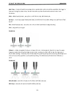
GENERAL GUIDELINES FOR VOLTAGE SENSE LEADS
Sense leads should be a
�
ached as close to the weld as prac
�
cal, and out of the weld current path when
possible. In extremely sensi
�
ve applica
�
ons it may be necessary to route cables that contain the sense
leads away from the electrode and work welding cables.
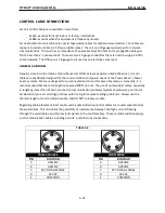
Voltage sense leads requirements are based on the weld process (See Table A.2).
TABLE A.2
PROCESS ELECTRODE VOLTAGE SENSING
(1)
67 LEAD
WORK VOLTAGE SENSING
(2)
21 LEAD
GMAW
67 LEAD REQUIRED
21 LEAD OPTIONAL
(3)
GMAW-P
67 LEAD REQUIRED
21 LEAD OPTIONAL
(3)
FCAW
67 LEAD REQUIRED
21 LEAD OPTIONAL
(3)
STT [1]
67 LEAD REQUIRED
21 LEAD OPTIONAL
(3)
RECOMMENDED FOR CABLES LONGER
THAN 75 FT.
GTAW
VOLTAGE SENSE AT STUDS
VOLTAGE SENSE AT STUDS
SMAW
VOLTAGE SENSE AT STUDS
VOLTAGE SENSE AT STUDS
(1)
The electrode voltage sense lead (67) is automa
�
cally enabled by the weld process, and integral to the
5 pin ArcLink control cable (K1543-xx).
(2)
When a work voltage sense lead (21) is connected the power source will automa
�
cally switch over to
using this feedback (if the auto sense feature is enable).
(3)
Nega
�
ve polarity semi-automa
�
c process opera
�
on WITHOUT use of a remote work sense lead (21)
requires the Nega
�
ve Electrode Polarity a
�
ribute to be set.
ELECTRODE VOLTAGE SENSING
The remote ELECTRODE sense lead (67) is built into the 5-pin ArcLink control cable and is always
connected to the wire drive feed plate when a wire feeder is present. Enabling or disabling electrode
voltage sensing is applica
�
on speci
fi
c, and automa
�
cally con
fi
gured by the ac
�
ve weld mode.
If the auto sense lead feature is disabled and the weld polarity a
�
ribute is improperly
con
fig
ured extremely high welding outputs may occur.
Summary of Contents for PIPEFAB CE
Page 18: ...PIPEFAB WELDING SYSTEM INSTALLATION A 3 FIGURE A 1 ...
Page 97: ......

