PIPEFAB™ WELDING SYSTEM
OPERATION
B-14
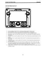
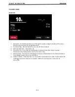
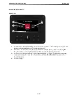
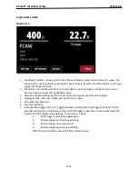
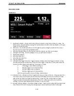
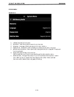
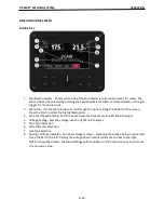
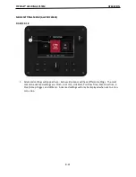
MIG HOME SCREEN
FIGURE B.11
1. Feedhead Indicator – Shows which side of the wire feeder is selected and ready for setup. The
ac
�
ve side can be selected by pressing the Feedhead Select Switch, Cold Feed Switch, or the gun
trigger for the desired side.
2. Menu Bar - Use the Menu knob to scroll through the op
�
ons along the bo
�
om of the screen.
Press the knob to select the highlighted op
�
on.
3. Wire Feed Speed Se
�
ng - Sets the desired wire feed speed, use le
�
knob to adjust.
4. Voltage/Trim Se
�
ng - Sets the voltage or trim, use right knob to adjust.
5. MIG Mode Selec
�
on.
6. Wire Type Selec
�
on.
7. Wire Diameter Selec
�
on.
8. Gas Type Selec
�
on.
9. 2-Step/4-Step Trigger Interlock - Toggles between 2-Step and 4-Step Trigger Interlock. 2-Step
provides weld power and feeds wire only when the trigger is depressed. 4-Step eliminates the
need to hold the trigger while welding. It operates in 4 steps:
1.
Close trigger and establish welding arc.
2.
Release trigger and con
�
nue welding.
3.
Reclose trigger near end of weld.
4.
Release trigger again to stop welding.
NOTE: No symbol will be shown if 2-Step mode is ac
�
ve.
10. Ul
�
marc/Pinch – Ul
�
marc and Pinch regulate the focus or shape of the arc. Values greater than
0.0 increase the pulse frequency while decreasing the background current, resul
�
ng in a
�
ght,
s
�ff
arc best for high speed sheet metal welding. Values less than 0.0 decrease the pulse
frequency while increasing the background current, for a so
�
arc good for out-of-posi
�
on
welding. The MIG mode will determine if Ul
�
marc is used or Pinch.
11. Synergic Voltage Indicator – Nominal voltage is shown. Lowering the voltage below nominal will
move the bar to the le
�
. Raising the voltage above nominal will move the bar to the right.
Summary of Contents for PIPEFAB CE
Page 18: ...PIPEFAB WELDING SYSTEM INSTALLATION A 3 FIGURE A 1 ...
Page 97: ......

