


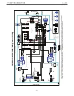


PIPEFAB™ WELDING SYSTEM
OPERATION
B-34
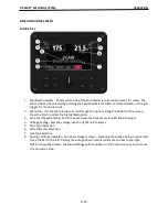
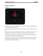
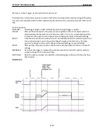
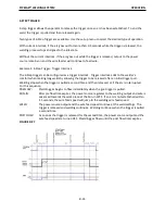
Example 2: 4-Step Trigger: Manual Control of Start and Crater
�
mes with Burnback ON.
The 4-Step trigger sequence gives the most
fl
exibility when the Start, Crater and Burnback func
�
ons are
ac
�
ve. This is a popular choice when welding aluminum because extra heat may be needed during Start
and less heat desired during crater. With 4-Step trigger, the welder chooses the amount of
�
me to weld
at the Start, Weld and Crater se
�
ngs by using the gun trigger. Burnback reduces the occurrence of wire
to s
�
cking into the weld pool at the end of a weld and condi
�
ons the end of the wire for the next arc
start.
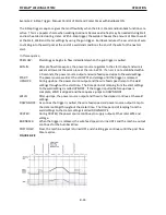
In this sequence,
PREFLOW:
Shielding gas begins to
fl
ow immediately when the gun trigger is pulled.
RUN-IN:
A
�e
r pre
fl
ow
�
me expires, the power source regulates to the start output and wire is
advanced towards the work piece at the run-in WFS. If an arc is not established within
2.0 seconds, the power source output and wire feed speed skips to the weld se
�
ngs.
START:
The power source welds at the start WFS and voltage un
�l
the trigger is released.
UPSLOPE:
During upslope, the power source output and the wire feed speed ramp to the weld
se
�
ngs throughout the start
�
me. The
�
me period of ramping from the start se
�
ngs
to the weld se
�
ngs is called UPSLOPE. If the trigger is pulled before upslope is
complete, WELD is skipped and the sequence jumps to DOWNSLOPE.
WELD:
A
�e
r upslope, the power source output and the wire feed speed con
�
nue at the weld
se
�
ngs.
DOWNSLOPE: As soon as the trigger is pulled, the wire feed speed and power source output ramp to
the crater se
�
ngs throughout the crater
�
me. The
�
me period of ramping from the
weld se
�
ngs to the crater se
�
ngs is called DOWNSLOPE.
CRATER:
During CRATER, the power source con
�
nues to supply output at the crater WFS and
voltage.
BURNBACK:
When the trigger is released, the wire feed speed is turned OFF and the machine output
con
�
nues for the burnback
�
me.
POSTFLOW:
Next, the machine output is turned OFF and shielding gas con
�
nues un
�l
the post
fl
ow
�
mer expires.
FIGURE B.28
Summary of Contents for PIPEFAB CE
Page 18: ...PIPEFAB WELDING SYSTEM INSTALLATION A 3 FIGURE A 1 ...
Page 97: ......


