PIPEFAB™ WELDING SYSTEM
INSTALLATION
A-32
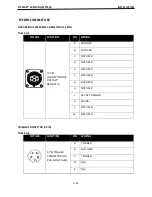
CONTROL CABLE CONNECTIONS
ArcLink Control Cables are available in two forms:
-
K1543-xx series for most indoor or factory installa
�
ons.
-
K2683-xx series when the equipment is frequently moved.
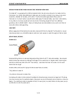
ArcLink/LincNet control cables are special high quality cables for digital communica
�
on. The cables are
copper 5 conductor cable in a SO-type rubber jacket. There is one 20 gauge twisted pair for network
communica
�
ons. This pair has an impedance of approximately 120 ohms and a propaga
�
on delay per
foot of less than 2.1 nanoseconds. There are two 12 gauge conductors that are used to supply 40 VDC
to the network. The
fi�
h wire is 18 gauge and is used as an electrode sense lead.
GENERAL GUIDELINES
Genuine Lincoln control cables should be used at all
�
mes (except where noted otherwise). Lincoln
cables are speci
fi
cally designed for the communica
�
on and power needs of the Power Wave
®
/ Power
Feed
™
systems. Most are designed to be connected end to end for ease of extension. Generally, it is
recommended that the total length not exceed 200
�
. (61 m). The use of nonstandard cables, especially
in lengths greater than 25 feet, can lead to communica
�
on problems (system shutdowns), poor motor
accelera
�
on (poor arc star
�
ng), and low wire driving force (wire feeding problems). Always use the
shortest length of control cable possible, and DO NOT coil excess cable.
Regarding cable placement, best results will be obtained when control cables are routed separate from
the weld cables. This minimizes the possibility of interference between the high currents
fl
owing
through the weld cables, and the low level signals in the control cables. These recommenda
�
ons apply
to all communica
�
on cables including ArcLink
®
and Ethernet connec
�
ons.
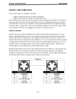
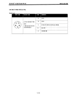
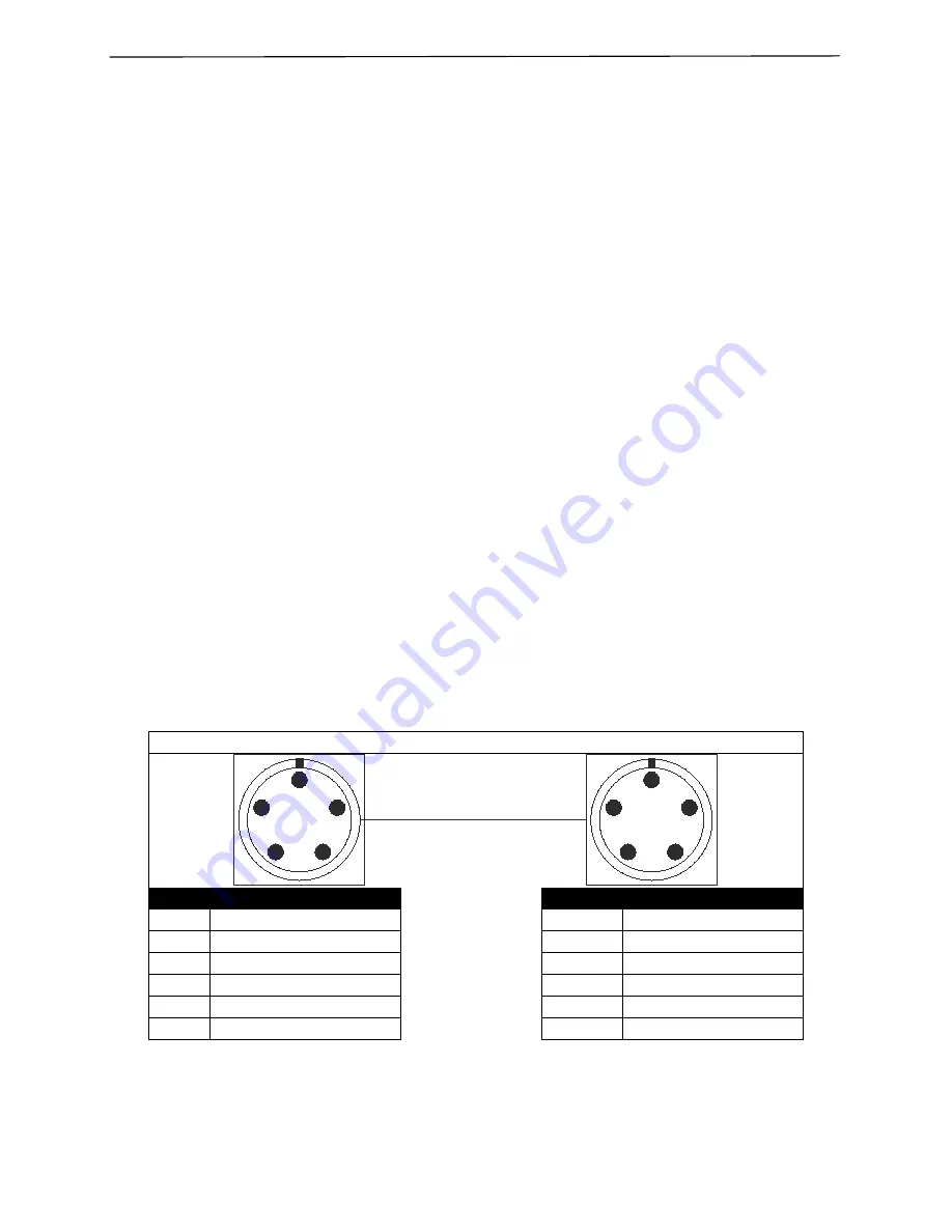
TABLE A.3
POWER SOURCE
WIRE FEEDER
PIN
FUNCTION
PIN
FUNCTION
A
ARCLINK
A
ARCLINK
B
ARCLINK
B
ARCLINK
C
67 VOLTAGE SENSE
C
67 VOLTAGE SENSE
D
40 VDC
D
40 VDC
E
COMMON
E
COMMON
A
B
C
D
E
A
B
C
D
E
Summary of Contents for PIPEFAB CE
Page 18: ...PIPEFAB WELDING SYSTEM INSTALLATION A 3 FIGURE A 1 ...
Page 97: ......


