PIP
E
FAB™ WELDING SYSTEM
INSTALLATION
A-11
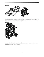
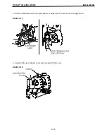
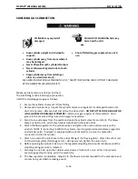
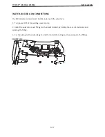
7. If the gun adapter requires guide tubes, install the correct size guide tube and secure with the set
screw.
FIGURE A.13
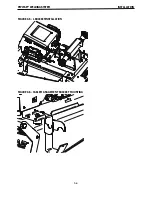
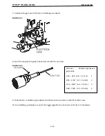
8. Assemble the sense lead to the new gun adapter. Orient the lead towards the rear of the gun
adapter.
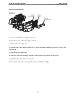
9. If required, assemble the gas hose to the gun adapter or the
fi�
ng on the feed plate and secure with
a hose clamp.
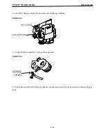
10. Assemble the gun adapter to the wire drive. Tighten the set screw once the gun adapter is at a 90°
angle.
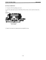
11. Bolt the electrode lead to the gun adapter, making sure to route the lead straight down.
FIGURE A.14
Wire size
Number of grooves in
guide tube
.023 – .045” (0.6 – 1.2 mm)
1
.045 – 1/16” (1.2 – 1.6 mm)
2
1/16 – 5/64” (1.6 – 2.0 mm) 3
.068 – 7/64” (2.0 – 2.8 mm)
4
Summary of Contents for PIPEFAB CE
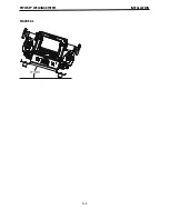
Page 18: ...PIPEFAB WELDING SYSTEM INSTALLATION A 3 FIGURE A 1 ...
Page 97: ......

