8. Lightware Device Controller
UBEX series – Matrix Application Mode – User's Manual
100
8. Lightware Device Controller
UBEX series – Matrix Application Mode – User's Manual
100
MA
TRIX APPLIC
A
TION MODE
Applied F-series endpoint firmware package: v1.4.1 | Applied R-series endpoint firmware package: v1.4.1 | Applied MMU firmware package: v1.2.1 | LDC software: v1.34.0b2
Step 3.
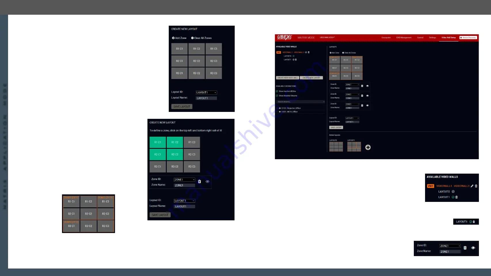
Add a unique name for the layout in the
Layout name
field, the
default name is LAYOUT1. The next step is defining the zones
where the contents will be displayed.
Step 4.
Click on the
Add Zone
button. Click on the upper
left corner of the zone at first, then click on the lower
right. A unique name can be added in the
Zone name
field, the default for the first one is ZONE1.
Define all zones on the video wall. In our example
three zones are created by the following way:
ZONE1
: R1 C1, R1 C2, R2 C1, R2 C2;
ZONE2
: R1 C3, R2 C3;
ZONE3
: R3 C1, R3 C2, R3 C3.
Legend: R1 C3 = Display in the Row 1 and Column 3.
The picture below shows all the defined zones:
Step 5.
Click on the
Save layout
button to complete the new layout.
The new layout is created
Step 6.
Complete the video wall. Click on the
(Activate)
icon next to of the
name of the video wall. When the icon changes to
and the name
changes to white, the video wall with the new layout becomes
active
.
Step 7.
Click on the
(Activate)
icon next to of the name of the layout. The
green
icon means the currently active layout.
8.19.4. Managing of the Layout and Zones
The new layout can be deleted by clicking on the
(Delete)
icon next to the name of the
layout in the Available video walls section.
All zones can be deleted by clicking on the
Clear All Zones
button.
Each zone can be deleted by clicking on the
(Delete)
icon in the zone
section. in the Available video walls section.
The zone can be identified by clicking on the
(Identify zone)
icon. See
Identify Stream / Identify Display


