2-68
Service Manual
7014-xxx
Escalating a fax issue to second-level support
Before contacting the second-level support, go to the SE menu on the MFP.and generate a Fax error file. This
file contains machine settings information and debug information that will help second-level support determine
the cause of a failure.
To generate the fax error file, perform the following steps:
1.
In a Web browser, type http://MFP ip address/se.
2.
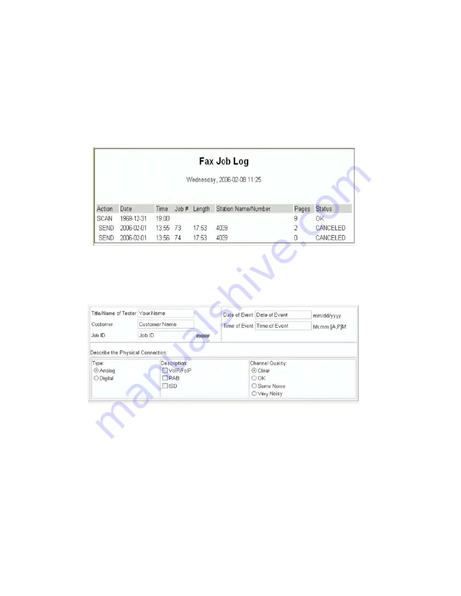
The MFP’s SE menu page will display. Click the “Dump Job History” link. The following displays:
3.
Write down the type of connection, the type of error, and the job in which the error occurred.
4.
In the Web browser address bar, type http://MFP ipaddress/se.
5.
Click
Report a Fax Problem
(A). The fax check list displays.
6.
Fill in the requested information. This is where you will type in the information you retrieved in step 3.
Second-level support can assist you if you have questions about the information requested on the page.
Note:
The fields requesting the code levels, model number, type of problem are auto-filled. If the information is
not in the fields, it can be retrieved from the SE menu. The SE menu can be accessed by pressing **411 on the
keypad or typing http://MFP ipaddress/se in a Web browser.
7.
After all the requested information is entered into the Fax Checklist Web page, press the
Submit
button on
the bottom of the page. A dialogue asking you to save the file will appear.
Note:
The file generated by the MFP is not automatically transmitted to second-level support. It is placed
on the computer desktop.
8.
Enter a name for the file, and indicate where you want to save the file.
9.
press
OK
. The file appears on the desktop.
10.
E-mail the file to second-level support.
Summary of Contents for X46 Series
Page 10: ...x Service Manual 7014 xxx...
Page 15: ...Notices and safety information xv 7014 xxx...
Page 16: ...xvi Service Manual 7014 xxx...
Page 22: ...xxii Service Manual 7014 xxx...
Page 162: ...3 56 Service Manual 7014 xxx...
Page 174: ...4 12 7014 xxx 2 Remove the three screws B securing the top of the controller shield B...
Page 184: ...4 22 7014 xxx 6 Remove the screw D from the gear E 7 Remove the plastic bushing F...
Page 194: ...4 32 7014 xxx 2 Carefully pull the scanner front cover away from the tub assembly...
Page 207: ...Repair information 4 45 7014 xxx 5 Remove the three screws B from the left door mount B...
Page 221: ...Repair information 4 59 7014 xxx 7 Open the front access door and remove the lower paper guide...
Page 256: ...4 94 7014 xxx 14 Remove the three screws A from the left rear frame assembly A A A...
Page 278: ...4 116 7014 xxx...
Page 290: ...7 2 Service Manual 7014 xxx Assembly 1 Covers 3 11 7 13 5 16 9 15 2 10 6 17 4 12 8 14 1 17 18...
Page 292: ...7 4 Service Manual 7014 xxx Assembly 2 Imaging 3 11 7 13 5 16 9 15 2 10 6 4 12 8 14 1...
Page 294: ...7 6 Service Manual 7014 xxx Assembly 3 Tray assemblies 3 2 1 5 4...
Page 296: ...7 8 Service Manual 7014 xxx Assembly 4 Electronics 2 1 10 11 12 7 13 9 6 14 2 5 8 3 4 16 15 17...
Page 302: ...7 14 Service Manual 7014 xxx...
Page 306: ...I 4 Service Manual 7014 xxx...
Page 309: ...Part number index I 7 7014 xxx 56P0558 RJ11 Cable w Toroids 7 12 7377732 Relocation Kit 7 12...
Page 310: ...I 8 Service Manual 7014 xxx...


